
Introduction
Launch Model Builder
Windows
Inorigo Launcher is used to Launch the Model Builder and Application Builder Modules. Upon first use, download and install the inorigo Launcher. User Menu > Help > Download Launcher
Once the Launcher has been installed, access Model Builder through the workbench. Inorigo Launcher will automatically download and install the necessary Java files to your computer.
Troubleshooting
– Nothing happens when I click the Model/Application Builder icon in Workbench
Ensure that your browser and operating system permits inorigo Launcher to start from your browser.
Other Operating Systems
Java Webstart is used for all other operating systems.
Context
Information domains and units
Information units that relate to each other are grouped into information domains.
The information domains to be used are Generic Model, Process (only for methods) and Basic Data. The ones visible in the application may vary depending on installation.
The domains Person, Organisation, Document and Codes and Standard are legacy domains, only supported for customers with existing data.
In all domains but one, there are two kinds of information units, definition units and individual units. Setting up specific information models is done by creating instances of the units. The definition unit defines the behavior (attributes, possible relations and associations) of individual units with that definition. The definition unit may be viewed as a template for the individual unit.
The Generic Model domain has two definition units; Generic Type and Generic Unit. Both units work as definition units. Generic Type is the definition for Generic Unit and Generic Unit is definition for Specific Unit. Thus, behavior defined on type level must be followed on Generic Unit level. Behavior defined on Generic Unit level must be followed on Specific Unit level.
Generic Model
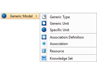
The following units resides within the Generic Model
 Generic Type
A generic type is a categorization of different kinds of generic units.
A Generic Type:
- Can not have a definition
- Can, but must not have super-classes (Generic Type)
- Can, but must not have sub-classes (Generic Type)
- Can, but must not have instances (Generic Unit)
 Generic Unit
A generic unit is a well defined, well recognized and delimited unit with a specific function and physical and/or logical features.
A Generic Unit:
- Can, but must not have a definition (Generic Type)
- Can, but must not have super-classes (Generic Unit)
- Can, but must not have sub-classes (Generic Unit)
- Can, but must not have instances (Specific Unit)
 Specific Unit
A specific unit is a fully specified unit. It is used to simplify communication through a given denotation (code) to secure a given form, feature specification and function. An example: the ISBN code is the denotation for a certain book, where the code is an identifier for the binding, publisher, date of publishing etc. Commonly used synonyms are product item, product code, part number and article number.
A Specific Unit:
- Must have a definition (Generic Unit)
- Can not have sub-classes
- Can not have instances
 Association Definition
An Association associates other units; Generic- and Specifc Units as well as other Associations. It is a nameless unit, identified only by the units it associates.
The Association Definition defines its instances, Associations. The definition allows you to specify how the instance should be presented based on perspective. If you for instance have created a definition that contains two attributes, Company (Organization) and Employee (Person) and you name the definition Employment, you can specify that from the person’s point of view, the association instance should be presented as Working at while from the organization’s point of view it is is employed. See Associations for details. Association Definitions may be marked as abstract (on the general tab) in which case it is not possible to instantiate them. You may also define constraints for your associations, e.g. a certain number of attributes that constitutes a unique key.
An Association Definition:
- Can not have a definition
- Can, but must not have super-classes (Association Definition)
- Can, but must not have sub-classes (Association Definition)
- Can, but must not have instances (Association)
 Association
An Association is an instance based on an Association Definition. The instance is a nameless unit with the unique ability to changes appearance depending on the perspective it is viewed from. See Associations for details.
An Association:
- Must have a definition (Association Definition)
- Can not have sub-classes
- Can not have instances
 Resource
An object stored in digital format.
A Resource:
- Can not have sub-classes
- Can not have instances
 Knowledge Set
The Knowledge Set Builder is a web based module through which you join multiple search queries to create a flat subset of the knowledge in the Model Builder. The subsets are called Knowledge Sets and are in many ways similar to flat tables. Knowledge Sets can be reached via the APIs and integrated in inorigo Applications or other similar tools.
Process
A process is a change of entity states.
 Process Unit Definition
A process unit definition is a definition of well delimited units of change that can be used to create Methods.
 Method
Methods is a visual programming language that can be used in inorigo® to manipulate data where Expressions does not suffice. Method can be used for a variety of purposes; integration, import or export, calculations, validation, messaging and so on.
Geography
Geography is a division of the surface of planet Earth. This is usually done on geopolitical basis.
 Geographical Area Definition
A geographical area definition is a categorization of the different kind of surface divisions, for example country, city, district, province and state.
 Geographical Area
A geographical area is defined by a geographical area definition, for example Sweden, Stockholm city and Stockholm municipality.
Attributes
Attributes comes in two different flavors, the ones identified by the arrow icon ![]() and the diamond icon
and the diamond icon ![]() . The first kind is unit specific, defined in the database and fundamental to the unit. It is not possible to change their behavior in the application. Examples of attributes are Name, Code and Unit Id.
. The first kind is unit specific, defined in the database and fundamental to the unit. It is not possible to change their behavior in the application. Examples of attributes are Name, Code and Unit Id.
The other kind of attributes is configurable and defines the unit further. These attributes may be set up by the user in the application. An attribute may for example be a simple string or integer (primitives), but may also point to other information units.
Important!
Customer information models does not support complex attributes anymore. Support has been kept in legacy code to avoid upgrade issues. It is strongly recommended to replace complex attributes.
The difference between an attribute pointing at another unit and a relation between two units is that the attribute defines the unit, whilst the relation is just that, a relation between the two. A person is defined by its birth date, height and hair color, but not by its children, with whom the person has the relation parent to (and the child has the relation child of).
Attributes are set up on the Information domains and units. When an individual unit is created, a definition unit is chosen to give the individual unit its behavior.
An example: A Generic Unit is created and named Company. An attribute, Organisation Number, is defined on the definition unit. Then an individual unit, defined as a Company, is created and named Ortelius Management AB. Ortelius Management AB inherits the attribute Organisation Number and is prompted to set a value to it.
The navigator icon for an attribute value is a diamond ![]() .
.
References
When an attribute points at another information unit (rather than a primitive), a link is created to enable search and navigation. The object being pointed at (i.e. referenced) also gets a link, a ![]() Reference (previously known as Attribute Reference), to enable search and navigation to all objects pointing to it with attributes.
Reference (previously known as Attribute Reference), to enable search and navigation to all objects pointing to it with attributes.
The navigator icon for aReference is the ![]() Attribute diamond complemented with left arrow
Attribute diamond complemented with left arrow ![]() .
.
Unit Relations
Information exists in relation to other information. The relation between two units is a ![]() Relation unit. The relation may hold attributes, such as a sequence, but no attributes. A relation is either directed or undirected. A directed relation may be viewed from two directions, up or down, and is named accordingly, for example
Relation unit. The relation may hold attributes, such as a sequence, but no attributes. A relation is either directed or undirected. A directed relation may be viewed from two directions, up or down, and is named accordingly, for example ![]() Consist of (down) /
Consist of (down) / ![]() Is a part of (up),
Is a part of (up), ![]() Parent to (down) /
Parent to (down) / ![]() Child of (up),
Child of (up), ![]() Followed by (down) /
Followed by (down) / ![]() Preceded by (up). An undirected relation is bidirectional and is named regardless of point-of-view, for example the Has borders to-relation between countries and the Cooperates with-relation between companies.
Preceded by (up). An undirected relation is bidirectional and is named regardless of point-of-view, for example the Has borders to-relation between countries and the Cooperates with-relation between companies.
Some relations have a predefined behavior in the application. The specific behaviors of these relations are explained below.
Can NOT be combined with
The relation Can NOT be combined with is bidirectional. It has a predefined behavior in the inorigo® Product Configurator only. First, units with this relation are shown in the Illegals-palette in the Product Configurator. Secondly, the product generator does not generate combinations of units that have this relation.
 Classifies /
  Is a kind of
The relation Classifies / Is a kind of can only be used between units of the same kind. The resulting structure is called a classification structure and it enables attributes to be inherited from one unit to another. In the generic model domain it also enables the composition structure to be inherited. This is a very powerful tool when similar information models form patterns that may be abstracted and reused instead of redefined and duplicated.
For example, both Car and Motorcycle are a kind of Vehicle (Vehicle classifies both Car and Motorcycle) and as such, they have common behavior. They both have an engine and wheels for example. To avoid defining the same information in many units, the information common to both Car and Motorcycle is defined in the abstracted unit Vehicle and reused. This way, only information specific to a Car or Motorcycle is defined on the specific vehicle, such as steering wheel or sidecar.
Consist of / Is a part of & Contains / Included in
The relations Consist of / Is a part of and Contains / Included in has a predefined behavior in the generic model domain only. Using any of the relations in the other domains does not result in any specific behavior.
The relations are composition relations, relations describing how a unit is composed. Generic and Specific Units have the additional tabs Product Composition and Product Configurator . Both tabs are based on unit composition. The Product Composition tab shows what the unit consists of and contains, i.e. the units the unit has the relation Consist of and Contains to. The Product Configurator uses the composition relations to decide what configurator palettes to show. To generate Specific Units the generator also bases its functionality in the composition structure.
Implements / Implemented by
The predefined behavior of the relation Implements / Implemented by controls an interface mechanism. It is a mechanism for attribute inheritance outside the classification structure and it gives the ability to apply unit characteristics that do not conceptually fit in the classification structure. This feature is applied in the generic model domain only.
An example of good use of this relation is the definition of a price. Let’s say it is essential to hold the price for many, but maybe not for all, of the functional units of a cabinet. It is not conceptually logical to let all functional units, that a price is relevant for, reside in the same classification structure; they simply are not of the same kind. A cabinet door is not of the same kind as the cabinet body. To be able to give those two units the same attribute without having to define it twice, the use of interface is applied.
It is important to remember that an interface should only be used when the attribute inherited truly is an attribute, and not a relation. And that it should only be used when that attribute is conceptually wrong in a classification structure.
Varies / Varied by
The relation Varies / Varied by is used to let units act as an aspect on other units in certain contexts. An aspect is a phenomenon where one unit may affect the attribute values of another unit. No unit is an aspect per definition, but may act as one.
For example if a cabinet is manufactured in different widths, the width concepts (named for example 600 and 800) specify the width attribute of some of the cabinet parts. The width of a cabinet body for example is 599 mm in the 600 concept and 799 mm in the 800 concept, whereas the cabinet front only is 596 mm / 796 mm.
This could be accomplished in an ordinary classification structure, where concepts Cabin 600 and Cabin 800 are classified by generic unit cabinet, and the attribute values are set appropriately. What the classification structure can’t accomplish is to define the width of a front in a 600 concept more generally, so that all fronts, regardless of what furniture (or otherwise) they are manufactured for, have a certain width. With aspects, the drawer unit front automatically gets the right width for the 600 and 800 concepts, without having to create the concept Drawer 600 and Drawer 800.
Validated by
This relation is specific to the Product Configurator which uses this relation that is connected to the Generic Unit to find a method and validate the generated specific unit (product). The method in question gets the list of specific units that constitutes the new product and is required to return a VALIDATION_RESULT as output. See Validate Bike by for details.
Price List / Price List for
This relation is dedicated to the Product Configurator as it uses it to retrieve the different price lists that are attached to this Generic Unit. For instance if you attach 5 units with the relation Price List, the generator will try and retrieve prices for each item in the BOM from every linked price list. This relation is intimately related to the #Find using -relation.
Find using
The Find using-relation is dedicated for the Product Configurator in a similar manner as the #Validated by -relation. This relation however is used to invoke the method which retrieves the price for a Specific Unit.
Concurrency in inorigo® Model Builder
The basic functionality of concurrency in inorigo® Model Builder is; when changes are saved in one place in inorigo® Model Builder, it is instantly available for all users.
Temporary Matrix
The changes in the matrix will be visible for all users after the data has been saved.

In the scenario above none of the data entered will be visible for the user until it has been saved.
If the Child 1 is changed and saved it will not prompt an update of the entire matrix but just the object that has changed. I.e. if the user to the left changes the Child 1, Child 2 won’t be updated for the user to the right.
If the user to the left and to the right both make changes in Child 1 and the user to the left saves, the changes made by the user to the right will be lost and updated with the changes made by the user to the left.
Navigator
All changes are instant in the navigator, there is no need to save when making a change. When working in the navigator and someone else is making a change you can instantly see your navigator being updated with the new data.
For example someone adds Child 3 to the structure below.
|
Your version before the child is added |
Your version after the change |
|---|---|
|
|
|


There is no need to make an update to see the changes made.
Product composition
The product composition tab has a slightly different functionality regarding concurrency. If you have the structure as shown in the picture above and open Parent, Child 1 and Child 2 next to each other in inorigo® Model Builder:

The rules are as follows:
- If you add a multiplicity to Parent it is visible for Child 1 and Child 2 at the moment you save Parent. The multiplicity is written in italic for Child 1 and Child 2 and bold for Parent meaning that the children’s value is inherited from the parent.
- If you already have set a multiplicity for Child 1 and set a new for Parent, the multiplicity for Child 1 doesn’t change. The value for Child 1 is written in bold, to denote that it is not an inherited value. If you remove the value for Child 1 it is replaced with the inherited value from Parent.
- If you changed the value for Child 1 and don’t save, and then change the value for Parent and save, the value entered for Child 1 is updated with the new value inherited from Parent.
- If you make a change in Child 1 or Child 2 no changes should be visible for any of the other two.
Hotkeys in Model Builder
Model Builder General
|
CTRL + O
|
Open by ID |
|
CTRL + F4 |
Close current tab |
|
CTRL + SHIFT + F4 |
Close all tabs |
|
CTRL + N |
New unit – if any unit is already opened in a tab, CTRL + N will per default create a new unit of the same data type. If no unit is open, CTRL + N reveals the new unit menu. |
|
CTRL + S |
Save changes to current tab |
|
CTRL + SHIFT + S |
Save changes to all tabs |
|
CTRL + SHIFT + C |
Copy unit in current tab |
|
CTRL + R |
Revert unsaved changes to current tab |
|
CTRL + D |
Delete unit in current tab |
|
CTRL + B |
Bookmark |
|
CTRL + M |
Toggle to Application Builder – if module is already open CTRL + M tabs to Application Builder. If not it opens the module. |
Temporary Matrix
|
CTRL + C |
Copy to copy and paste inorigo units, such as associations they need to be pasted to a field that accepts units of that type. |
|
CTRL + V |
Paste to copy and paste inorigo units, such as associations they need to be pasted to a field that accepts units of that type |
|
CTRL + X |
Cut to copy and paste inorigo units, such as associations they need to be pasted to a field that accepts units of that type |
|
CTRL + MOUSE1 |
Select Multiple Units |
|
SHIFT + MOUSE1 |
Fill down/up selection from first selection |
|
CTRL + SHIFT + MOUSE1 |
Fill down/up while keeping current selection |
|
CTRL + E |
Open current matrix in Excel |
|
CTRL + D |
Fill down Fill all cells in the current selection with the value from the top cell for each column |
Navigator/Search Panel
|
CTRL + C |
Copy to copy and paste inorigo units, such as associations they need to be pasted to a field that accepts units of that type. |
|
CTRL + V |
Paste to copy and paste inorigo units, such as associations they need to be pasted to a field that accepts units of that type |
|
CTRL + X |
Cut to copy and paste inorigo units, such as associations they need to be pasted to a field that accepts units of that type |
|
CTRL + MOUSE1 |
Select Multiple Units |
|
SHIFT + MOUSE1 |
Fill down/up selection from first selection |
|
CTRL + SHIFT + MOUSE1 |
Fill down/up while keeping current selection |
|
RIGHTARROW |
Expand tree |
|
NUM + |
Expand tree |
|
LEFTARROW |
Collapse tree |
|
– |
Collapse tree |
The Generic Model Domain
The Generic Model-domain is a bit different than the other information domains in the sense that this has three-level architecture, i.e. Generic Type, Generic Unit and Specific Unit. The modeling rules apply for this domain as well, i.e. if you specify an attribute on a Generic Type it can be used on its instances, i.e. a Generic Unit. The same rule applies to Generic Unit and Specific Unit.
Tip!
Since the Generic Model-domain is much more flexible than the other information domains, it is recommended that you use this information domain for all types of entities. You are for instance not able to specify arbitrary relations between entities which are from different domains. In a future version of inorigo® you should not be constrained to the pre-defined information domains, but rather be able to create your own.
How to work in the generic model domain
The Generic Model-domain was originally the Product-domain and is especially suited for product configuration needs. The best way to effectively define, maintain and evolve business products is to start defining very generic products on a high abstraction level. Work through the levels of specification and let the Product Generator produce variants from which to create low level items; Specific Units. If you want to use the Product Configurator it is recommended that you study the example inorigo® Product Configurator. This document is a walkthrough of all the major functionality in the Product Configurator including Product Composition and Product Generator functionality.
The Generic Model-domain is suitable for all information and you should not restrict the use of this domain to only contain product definitions and instances. The Generic Model-domain also contains the Association-object which can associate (or link) any type of inorigo® entities (even from other information domains) and be able to change appearance depending on the view perspective. This feature allows you to create powerful information models that are able to resolve and refine information directly presented to the user of inorigo® Model Builder.
Associations
There is a need to be able to create a unit that may relate, or associate, two or more other units. The nature of such an object is that it does not have a name (it is nameless), but that instead it is possible to show the object, a.k.a. association, in the inorigo® Model Builder depending on the perspective of the association’s unit. An Association is in essence a nameless object which has one or several attributes.
This chapter will cover all of the aspects of the Association Definition and its instances. This chapter will use an example to describe and visualize the behavior and functionality associated with Associations. The example will use the Employment example, where there are three main attributes involved: Person, Organisation and Role.
Association Definition
An Association Definition is not that different from any other inorigo® unit definition. It has a few extra attribute properties, but is in general the same. An Association is an instance of an Association Definition in the same manner as a Specific Unit is an instance of a Generic Unit.
Create a new Association Definition from the File-menu and name it Employment.

Set the attribute Name (Plural) to Employments and leave the attribute Abstract unchecked; these attributes will be explained later.

Go to the Attributes tab-tab and add five attributes: Employee, Date, Company, City and Employment Type
Note!
By default the attribute property Multiplicity is set to 1. In most cases this would be the proper setting since an association is dependent on its values, and cannot exist without them.

If you are following the example you may have noticed that there are additional attribute properties to set on an association attribute; these will all be covered in the chapter Association Attribute Properties.
Create a few Employees, Employment Types and Companies in order to be able to create an Association. If you right click on one of these entities in the navigator you will get the option to create an Association (instance).

Through the connections panel we can choose from all available connections from the selected association unit. Since we are attempting to connect an instance, all abstract units are disabled in this connections menu.

Notice that the menu item (Employment, Employee) is assembled by the name of the definition and the name of the attribute, i.e. if you select this option the new object will already have the attribute Person set to the one you have selected.

Select an City, Date, Company and an Employment Type and save the object.

By default an association is presented by concatenating all of the attributes.

However, this is not very intuitive nor informative, so you need to define a default presentation expression. Open the Connections-tab for the definition Employment and select the Association-node in the tree on the left hand side.

Enter the following expression in the Presentation-text field – @Employee + ” works at ” + @Company
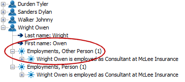
Save the definition and the presentation of the association will change, i.e. Wright Owen is employed as Consultant at McLee Insurance.

Note!
If you want to reference attributes that have spaces or non-character letters in their name, you need to replace them with underscore (_). The following characters are replaced:
- (space)
- – (dash)
- * (asterisk)
- ( (left parenthesis)
- ) (right parenthesis)
- . (dot)
- , (comma)
Please note that if you use a variable name within quotes, e.g. $get(@p0, "My Variable"), you should not replace them. The replacement is only done when you want to retrieve an attribute directly with the @-notation.
The attribute Name (Plural) is used as the default presentation for a bundle of associations, i.e. Attribute References.

Note!
The visualization in the navigator and the search panel differs, i.e. associations are listed under the heading Attribute References, while they in the navigator are grouped into separate bundles. See ticket #4089 for details.
This name also appears in the navigator when you see the attribute reference.

The name is constructed by the definition’s plural name and the attribute’s name.
Note!
If you would have two or more attributes with the same type on the same association, they would be split into different bundles. In the example below there is another attribute with the same class (Person) that is named Other Person, i.e. the person which has the perspective (Owen Wright) occurs twice in the same association but as different attribute values.
The attribute Abstract makes it possible to control instansiation of association definitions. A definition marked as abstract can not be instantiated. This promotes data accuracy in that it prevents users from creating instances of definitions that are only meant to act as classification parents.
When a definition is abstract, association (instance) is not an available connection on the Connections-tab. Nor does the definition appear in the context menu of the associated units. This will make the context menu faster to load and much shorter, only showing the associations that are supposed to be used.
Association Instance
An Association (instance) is no more than an ordinary inorigo® object with the difference that it has no name, i.e. you need to specify how it should be presented depending on the viewer’s perspective. The object can be used as any other inorigo® instance, e.g. Specific Unit, but an association it has extended capabilities.
Opening an association in the matrix has the same behavior as any other inorigo® object; it displays its attributes and relations.

However, when you display an object that is part of an association, the behavior changes slightly.

The matrix displays the Person-object which is part of an Employment-association. You cannot modify the association since that is an entirely different object, you are only able to see the association(s) that this Person is a part of.
Association Attribute Properties
The attribute definitions for an Association Definition has been extended with the following properties.
|
Attribute property |
Description |
|---|---|
| Instance of |
Only instances which has a particular type are applicable as attribute value. Applies in inorigo® version prior to 4.3.0 The reason to disable the valueset-functionality is that a valueset in inorigo® can be defined by one or several queries and / or adding random entries, i.e. there is no way of knowing if an inorigo® entity belongs to valueset, other than actually evaluating the valueset and check if it is there. This would entail that all valuesets were evaluated in order to find out whether an inorigo® entity can be part of a particular association or not. This functionality is required in order to fulfill the context menu behavior, i.e. when you right click on a Person for instance, the menu should present you with the different associations where the selected inorigo® entity can be part of. |
| Is a kind of | Only types which is a kind of another one are applicable as attribute values. All descendants (or sub-classes) are included. There is only one class that can have both Is a kind of and Instance of attribute property set and that is Generic Unit. A Generic Unit can be both an instance of a Generic Type and be a kind of another Generic Unit. If you specify both of the attribute properties, the result is the union of the both, i.e. only Generic Units that are an instance of and a kind of will be eligible as attribute values. |
| Valueset | Specify a set of values to use for this attribute. If a valueset is specified, this will override any value on “Instance of” or “Is a kind of” |
| Singular Name | Used when denoting an association from this attribute’s perspective (point of view), e.g. used in the context menu when to create a new association. |
| Plural Name | Used when denoting a bundle (collection) of associations from this attribute’s perspective (point of view), e.g. used in the search panel for attribute references. |
| Instance Presentation | How to present the association from this attribute’s perspective (point of view). |
To exemplify the Instance of-property you should create a new Generic Unit and name it Company. Link some of your Organisations to the newly created definition.

In this example the organisations McLee Insurance and Yucca Palms Ltd. is now an instance of Company. The remaining organisation Fringe Intl. Ltd. has no definition. Open the Association Definition Employment and change the Instance of-property to use Company as search criterion.

If you now try and create an Employment-association based on an organisation that is not an instance of Company, the option will no longer be applicable.

In the same manner only organisations which is an instance of Company are now available when editing the association.

The property Is a kind of is only applicable for types and the only Inorigo® entity that is applicable for both is Generic Unit, i.e. a Generic Unit can be an instance of Generic Type and a Generic Unit can be a kind of another Generic Unit. If you decide to specify both properties for a Generic Unit the criteria is interpreted as both needs to be true, i.e. only entities which is a kind of and is an instance of are valid.
The properties Singular and Plural Name are used to present the association from the attribute’s point of view. Open the Employment-attribute definition panel open the Company-attribute and modify the properties to Employee and Employees respectively and save the modification.

The Plural Name is now replacing the default presentation defined by the Association Definition‘s attribute Name (Plural). So from the Organisation’s point of view the association Employments is now presented as Employees.

Similarly when you want to create a new association from the organisation’s point of view, it is called Employee.

The Instance Presentation-expression defines how the association should be presented. From the organisation’s point of view we would like to present it as follows:
The presentation now changes in the navigator into Pippi Longstocking works as Hourly Employed.

The Instance Presentation is also used on the web when deleting units that have Nested Units.
Association Perspective
The association-object is specifically designed to change its appearance depending on the perspective. If we continue with the association example Employment with the attributes Person, Role and Organisation, you can imagine that from a particular perspective the association information has different levels of relevance.
If you for instance see Employment-associations from the organisation’s point of view, you are not interested in displaying the organisation; you already know that. The image below tries to visualize how the association is intended to work.

- Association Definition – default presentation
- You specify a default presentation on the association’s definition, i.e. if no other is defined, this one will be used.
- Person’s point of view
- From the person’s point of view there is no need to display the person, since that is already known. It is only relevant to display the organisation and the role.
- Role’s point of view
- In this example there is no real interest in viewing the association object with a particular perspective. If none is defined the default one is used.
- Organisation’s point of view
- Similarly there is no need to display the organisation, since this is already known. The only relevant information is person and role.
The association itself is no more than an object with a set of defined attributes.
In the same manner the references are displayed differently.

- Association Definition – default presentation
- When you look for Employment-associations you use the Name (Plural) attribute, i.e. Employments. When you want to create a new one you use the Name-attribute, i.e. Employment.
- Person’s point of view
- When a person looks for employments it is called Jobs, and when you get hired, a new Job is created.
- Role’s point of view
- The role has not specified a particular presentation, i.e. the default one is used.
- Organisation’s point of view
- From the organisation’s point of view it has a list of Employees and a new association results in a new Employee.
When you expect more than one, e.g. “look for” in particular, the attribute property Plural Name is used and when you expect one, e.g. “create new”, the attribute property Singular Name is used.
Association Inheritance
An Association Definition may be inherited, i.e. you are able to create new definitions which is a kind of the original one. This behavior is the same as for all definitions in inorigo®. Make sure you are able to create a Classifies / Is a kind of-relation between Association Definitions; add the relation in the Relation Specifier / Admin-tab.

Create a new Association Definition which is a kind of Employment.

Assign the name Permanent Employment and Permanent Employments for the plural name and save the definition.

Go to the Attribute-tab on the new definition object and you will notice that the existing attribute properties are in italic, which means that they are inherited.

Tip!
If a text is in italic in inorigo® Model Builder it indicates that the value is inherited.
Add a new attribute called Employment ID and make it an Integer. The new attribute is only available for instances that are defined by this definition.

We also need to override a couple of presentation rules in order to distinguish the association instances from one another. Open the Company-attribute and override the properties as follows:
|
Permanent Employment |
Employment |
|
|---|---|---|
| Singular Name | Permanent Employee | Employee |
| Plural Name | Permanent Employees | Employees |
| Instance Presentation | @Emplyoment_ID + ” ” + @Person + ” works as ” + @Role | @Person + ” works as ” + @Role |

The difference between an Employment– and Permanent Employment-instance is that a) it has a new attribute – Employment ID and b) the presentation from an organisation’s point of view has changed, i.e. the ID is displayed first.

If you create a few new associations based on the Permanent Employment-definition you will see that the presentation changes and that the new instances are grouped in a separate bundle.

Note!
If you have specified a specific Singular Name for the top level class, let’s say Job from the Person{}’s point of view. This name will override the default presentation, i.e. _Permanent Employment, Person will be Job. However, the name is also inherited, i.e. if you want to create a Permanent Employment or an Employment from the Person‘s perspective there will be two choices with the same name.

You need to override the name in the sub-class to distinguish the choices.

Association Constraints
You have the opportunity to add constraints to an association definition. In particular you want to be able to prevent duplicate records, i.e. an association with exactly the same values are identical and therefore is a duplicate. The example constraint below depicts a constraint where you’ve added all of the attributes to the constraint: Employee and Company.

- Name
- A description of the constraint. Mainly used to inform the user of which constraint that has been violated.
- Attributes
- A list of attributes that is part of the constraint. Only attributes which have the multiplicity equal to 1 are allowed to be part of the key.
- Crosswise Unique
- If you have two attributes of the same class, you can specify that the attribute values are evaluated crosswise. Assume that you have the association definition Collaborates with, which contains two attributes of the class Company. If you check the Crosswise Unique-checkbox the constraint will check for the reversed relation as well, i.e. if A collaborates with B, the reversed relation (B collaborates with A) is considered to be equal to the first one.
- Enforce
- If the Enforce-option is disabled, you will be able to override the constraint, i.e. you will get a warning when you add a new association that violates the constraints, but you have the possibility to create it anyways.
Warning!
Allowing duplicate entries is in most cases a mistake, i.e. you invite the user to add duplicate entries.
- If the Enforce-option is disabled, you will be able to override the constraint, i.e. you will get a warning when you add a new association that violates the constraints, but you have the possibility to create it anyways.
If you try to add a new association which already exist, you will get the following error message.

If you uncheck the Enforce-option, you will only get a warning.

You may not override constraints in sub-classes, i.e. the association definition Permanent Employment may not alter the All-constraint. However, the sub-class is allowed to add constraints to the definition.

Since the Permanent Employment adds the attribute Employment ID, the new (unique) constraint checks that the combination of Company and Employment ID is unique. Please note that the inherited constraint is not editable.
Note!
All constraints, including inherited ones, are evaluated when you create a new association.
You can also change the sequence of the constraints to make sure that one constraint is evaluated before another one. However, all constraints which have the Enforce-option set to true, will be evaluated first, i.e. there is no need to evaluate any warnings since validation will fail anyway. You should also bear in mind that the sequence may become difficult to predict if you have several levels of inherited constraints.
Build a product model
Building a product model is done in three steps:
- Compose the product on a functional level (with functional units).
- Define the product concepts (with concept units), based on the functional model.
- Generate and configure the specific units.
The strength in separating the general function of things from the more organisation specific function of things is that it enables reuse of basic functions at the same time as it enables an extremely competent comparison between in-house and/or competitor products, as they both point into the same basic functions.
The functional unit model represents the general function of things and should only contain just that – general functions. No trademarks or brand specific names should be present. The conceptual model, on the other hand, is where the trademarks, proper nouns and brand- and organisation specific terms belong. It is here, that organisation specific behaviors and compositions are defined.
Steps 1 and 2 are most effectively carried out in the product composition tab, whereas the last step may be carried out in the product configurator.
The Product Composition Tab
The product composition tab shows unit compositions. With composition we mean the unit and all the other units it consists of or contains (i.e. has the relation Consist of or Contains).
The composition tab is different from the navigation tab in its ability to show inherited compositions, define more complex models with replaced nodes and work with aspects. It doesn’t, on the other hand, show any other relations than the composition relations.

The values in italic are inherited values, while the ones in bold are specified in the current composition. The item column in the grid shows the compound unit in a tree structure.
The position column allows the user to specify the position of the unit in the model. If a Car has several wheels, for example, it may be interesting to specify left and right wheel, as they may be manufactured differently. The multiplicity column allows the user to specify how many units the composition should have.
The value column is only editable for attributes and allows the user to set a fixed attribute value valid in the current composition only. The exception to that rule is if the composition itself is inherited (through classification). Then the values are inherited as well. This is the equivalent of modifying the attribute definition in the [Attributes tab].
To see the unit attributes, check the setting Show Attributes in the Filter menu to the left.

|
Name |
Description |
|---|---|
|
Name |
Description |
| Show Interfaces | If attributes are inherited from interfaces, these are shown. The filter is initially unchecked. |
| Show Attributes | Initially unchecked to hide the attributes in the structure. |
| Show Replaced Nodes | Initially checked to show replaced nodes. |
| Compact | Initially checked to hide the relation name in the structure. |
The subsequent columns to the right of the value column show aspects categorized by aspect type. The aspects shown are defined in the Aspects menu to the left. It has some basic filtering options, with the supplement of choosing which aspects to show.

The Aspects menu show the aspects, categorized by type, which may act as aspects on the current composition. Only those generic units that the unit is Varied by are shown.
To show all aspects of a certain type, click the checkbox in front of the type. To show only assorted aspects within a type, click the plus button ( ![]() ) to expand the aspects and click the checkbox in front of the aspects to show.
) to expand the aspects and click the checkbox in front of the aspects to show.
Filter out aspects by writing any part of their name in the text field above the list. All aspects that does not contain the characters written, will be hidden.
The Product Configurator
The product configurator is primarily used to define what product parts that may be combined into a specific unit or concept, or to search for specific units (or concepts) that a part is used in. It may also be used for educational purposes, since it very clearly shows how products may and may not be modeled according to business rules.

At the top of the tab you have access to the Product Generator. The purpose of the Product Generator is to generate combinations of products, based on the choices made in the configuration units below. The type of units generated is of the same kind as the unit the configurator is opened for, i.e. the current tab unit.

If auto start is checked, the generator starts when the first unit that is a part of the current tab unit is selected (as opposed to selected aspects).
Note!
With only aspects selected, the generator would have to combine everything classified by the tab unit, and that would potentially take a very long time and would most likely not be very meaningful.
If auto start is not checked, the generator is started by pressing the start button. It may also be stopped at any time by pressing the stop button. To generate a specific unit number, a method, by which the number is generated, must be chosen. The method generating the numbers points to a method defined in the methods tab in a Process Unit Definition. The user must have the user setting “Show method tab” to be able to see the drop down Method for Item no.
The generator part of the configurator is divided into two sections, the list of generated units to the left and the selected unit composition (*B*ill *O*f *M*aterial) to the right. The first column shows a warning if there is a potential problem with the unit. A warning is issued if: Actual serial number does not match generated number, or Specific unit(s) with matching serial number and different structure is found. If no warning is issued, the first column is used to show an arrow for selection. See also Product generator log for messages during product generation.
The specific unit column shows if the unit is a specific unit or not. A check indicates that the unit is a specific unit, the absence of a check that it is not. To create or remove a specific unit, just check or uncheck the checkbox. Right clicking a row and choosing Create article / Delete article results in the same action (visible in the checkbox). The change is immediately saved. It is also possible to select many rows and either right click and choos action or pressing spacebar, which toggles selected checkboxes. Toggling the checkboxes result in product being created (checked) or removed (unchecked).
The Unit ID column shows the Specific Unit id. If the row represents an existing specific unit, the ID (if any) is shown. If the row represents a generated unit, the number generated by the chosen ID-method is shown (if any). Read about potential ID problems in the text above the first column. Furthermore, while the row represents a generated unit, the ID column is editable, to enable overriding the generated ID. If the ID should be changed on an existing specific unit, delete the specific unit, edit the ID and create the specific unit again.
The Name shows the generated name. The name generated is based on the functional unit name plus the combination of aspects. Selecting a unit shows its composition in the right section grid.
The Functional Unit column in the grid shows the compound unit in a tree structure, with the appropriate icon on each row. The Unit ID column shows the specific unit ID, if the row unit has one.
The Multiplicity column shows the number of units each row has in the composition. The Position column shows the given position of a unit in the composition. The bottom row in the composition grid is a summary row.
Product configurator using templates
Templates what are they?
Templates are previously generated Specific Units (Products). The Product generator can use Specific Units as templates for generating new variants.
Finding and selecting Templates
In Product Configurator show and pin the Templates panel (as shown below). A standard search panel is loaded, prepared for finding Specific Units for your current definition. Enter search criteria, press the Search button and select one or several Units in the result list.


Creating variants
As the user selects the desired template(s), below as blue bikes, the configurator automatically marks and selects the corresponding definitions.
Note!
All aspect selections are cleared to avoid confusion.
Select new aspects to be used for creating variants, below the Touring bike. When started the Generator will calculate what aspects were used to create each template Unit and replace the corresponding aspects by the aspects selected by the user. As shown below, the new attributes are applied in the BOM when the Generator has executed.

Product Configurator using Templates
Templates what are they?
Templates are previously generated Specific Units (Products). The Product generator can use Specific Units as templates for generating new variants.
Finding and selecting Templates
In Product Configurator show and pin the Templates panel (as shown below). A standard search panel is loaded, prepared for finding Specific Units for your current definition. Enter search criteria, press the Search button and select one or several Units in the result list.
Creating variants
As the user selects the desired template(s), below as blue bikes, the configurator automatically marks and selects the corresponding definitions.
Note!
All aspect selections are cleared to avoid confusion.
Select new aspects to be used for creating variants, below the Touring bike. When started the Generator will calculate what aspects were used to create each template Unit and replace the corresponding aspects by the aspects selected by the user. As shown below, the new attributes are applied in the BOM when the Generator has executed.
Graphical user interface
Application Menu
![]()
The application menu shows at the top of the application. It allows managing fundamental features in the application, such as creating a new unit and saving it. Further functions are for example the ability to change context, language and handle the application windows.
Application menu - File
The file menu consists of the following menu items:
|
Icon |
Name |
Shortcut |
Description |
|---|---|---|---|
| Open | Shows a submenu that allows the user to choose what kind of unit to open. As the unit is chosen, the application search tab, with that unit pre-selected, is shown. | ||
|
|
New | Shows a submenu that allows the user to choose what kind of unit to create. As the unit is chosen, a new information unit tab for that kind of unit is opened. | |
|
|
Save | Ctrl + S | Saves the current tab unit. |
|
|
Save All | Ctrl + Shift + S | Saves all units that are changed but unsaved (the ones with an asterisk (*) in the tab header). |
|
|
New | Ctrl + N | Opens a tab for a new unit of the same unit as the current tab unit. |
|
|
Delete | Ctrl + D |
Deletes the current tab unit. Note! Nothing is ever physically deleted in inorigo® Model Builder; it is merely marked with a date and time that the record is valid to. This is to enable traceability and statistical usage of deleted data.
|
| Copy | Ctrl + Shift + C | Copies the current tab unit. | |
|
|
Reload | Ctrl + R | Reverts the current tab unit to the state of the last save. |
|
|
Bookmark | Ctrl + B | Adds the current tab unit to the bookmarks menu. |
| Open by id… | Ctrl + O | Opens an entity identified by the unique Global identifier saved in database. | |
| Switch User… | Opens the login window to allow the user to login as a different user. The current user is logged out. | ||
| Exit… | Exits the application. |

Application Menu - View
The view menu consists of the following menu items:
|
Icon |
Name |
Shortcut |
Description |
|---|---|---|---|
| Current Users | Opens a window listing all users (and the engine) running that same instance, together with the context the user is logged into. | ||
| Menu | Slides open the application menu tab. To close it again, click somewhere outside the menu or click the minimize icon in the menu header. | ||
| Search | Ctrl + F | Slides open the application search tab. To close it again, click somewhere outside the menu or click the minimize icon in the menu header. | |
| Bookmarks | Slides open the application bookmarks tab. To close it again, click somewhere outside the menu or click the minimize icon in the menu header. |
Application Menu - Tools
The tools menu consists of the following menu items:
|
Icon |
Name |
Shortcut |
Description |
|---|---|---|---|
| Export to XML… | Exports the current tab unit navigator content to XML. Only those units explicitly expanded in the navigator are included in the export. This item is only enabled when a tab unit navigator is the current tab. |
||
| Clear Cache | Only available to administrators. Empties client- and server memory to enable reload of all units from the database. | ||
| Import and Export | Holds two sub menu items, Import… and Export… Import… allows the user to open a file to import data. The file to import must have been created by the inorigo® Model Builder Export… function below. Export… exports the current tab unit to a file. The alternative Export Entire Structure … includes all information surrounding the object, and the information surrounding the surrounding objects and so on. This may end up to be a lot of information; so much that the application may not be able to handle it. Therefore, use this alternative with caution! |
||
| Integration Log | Shows the log of all (Process domain) integration method jobs run, see inorigo® Integration Setup for details. | ||
| Integration File Manager | Allows you to manage files in the designated (file) integration directory, see Integration File Manager for details. | ||
| Task Execution… | Opens a window to execute tasks. |
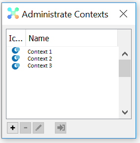
Administrate Contexts…
Opens the Administrate Contexts window.
1. To create a new context, press the New-button and fill in the New Context-dialog.
2. To delete a context, select the context to delete and press the Delete-button.
3. To edit a context, select the context to edit and press the Edit-button.
4. To change context, select the context and press the Go To-button.
Send Message…
Any user may send a message to any one or all of the other logged on users. Receiving a message, a user may choose to reply the sender only or reply all users.
A message sent back and forth will appear almost like a mail correspondence, but will not be saved. The moment the message window is closed, the message information is lost.

Application Menu - Options
The options menu consists of the following menu items:
|
Icon |
Name |
Shortcut |
Description |
|---|---|---|---|
| Context | Shows a submenu with contexts to enable changing current context. | ||
| Navigator | Sets the navigator filter for the current user. The settings are stored as a user preference and will remain between sessions. Since v2.2 | ||
| Preferences… | Opens a window with the current user as a shortcut to changing current user preferences. | ||
| System Settings… | Shows the settings for the context, client, system, computer and server. |
Report Error
The Report Error-function requires that you have access to the internet since you will be presented with the Ortelius Issues Tracking system.
Each inorigo® installation comes with either a default user or a user provided by Ortelius. The user is set in the Issue Tracking settings section. You also have the opportunity to login with personal credentials, in order to do so, you have to select the Manual Login for Bug Reporting-flag on the inorigo® user. You will then be presented with a login page instead of the automatic one.
The Issue Tracking System is intended to facilitate the communication with inorigo® users and to be able to track and monitor progress of bugs and assorted issues.
The list below describes the different fields available in the Issue Tracking System.
|
Name |
Description |
Mandatory |
|---|---|---|
| Tab: Quick info | ||
| Summary | A summary describing the ticket. | |
| Severity – Urgency | A status describing how urgent the matter is.
|
|
| In addition to the severity there is also a status requesting how soon the problem needs to be fixed. | ||
|
||
| The general process for bugs, if the severity is high enough, is that they will be fixed in the next maintenance release, e.g. 2.6.5. A maintenance release can be issued within a short period of time (days), unless any unforeseen circumstances. If a bug is deemed to be minor, it will be applied to the next release of inorigo, e.g. 2.7, which is released 3 times a year. The problem may also be considered to be an enhancement and / or change, and if this is the case, it will be applied in a future release. | ||
| Reproducible | How often the problem occurs.
|
|
| Steps to reproduce | A description on how to reproduce the problem. It is vital to describe the problem in detail, otherwise the helpdesk officer may not be able to reproduce the problem and needs to request addition information which in turn leads to longer lead time. | |
| Actual result / error message | A description of the actual result and an (optional) expected result. | |
| Additional info | Additional information not directly related to the issue detected in inorigo®. It may concern external circumstances such as network problems or other relevant information. | |
| User Email | Can be provided if the reporter wants to be contacted directly by email and reports the error as a system user. If reporting with personal credentials this information is superfluous. | |
| Full name | Can be provided if the reporter wants to be contacted directly. The user name automatically provided from inorigo can sometimes be cryptic. If reporting with personal credentials this information is superfluous. | |
| Tab: Application info | This tab is automatically populated with data if you report the bug from inorigo® Model Builder. However, if you login to the tracking system manually, you have to supply the information. | |
| Communication Host | The URL to the inorigo® Server. | |
| Application Name | The name of the inorigo® application. This is important if you have more than one inorigo® Server installation on the same sever. | |
| Application Version | The inorigo® version, e.g. 2.6.5. This is vital in order to be able to reproduce the problem. This can found on the inorigo® start page or under the Help-menu. | |
| Application Build | The build id, e.g. 8564. This can found on the inorigo® start page or under the Help-menu. | |
| Application Context | The inorigo® Context where the problem occurred. | |
| Application Database | The name and host of the inorigo® database. This can be found on the About-dialog. | |
| Client Java Version | The Java version used by the client. This information is useful to detect compatibility issues between JVM-versions. | |
| inorigo® User Name | The inorigo® user name. This is important if the issue concerns authorization or inorigo® credentials. | |
| Error Message | An error message or stacktrace provided by the inorigo® application. | |
| Additional info | For Ortelius Support internal use only |
Preferences
Preferences-tab
The Preferences-tab allows the user change settings for the client application, such as language and locale. The table below describes the different settings.

The Preferences-tab inherits Client-settings which is available in the System Settings-dialog. Not all settings will be modifiable in the preferences dialog, since they are applied before the user is known. User settings, i.e. preferences, will by default override values set in Client-settings.
|
Name |
Applies to |
Comment |
|---|---|---|
| Icon | User control set | Changes the icon of the user controlset, i.e. the object that contains the preferences information. |
| ownerGID | – | Read only attribute of user settings. |
| controlesetGID | – | Read only attribute of user settings. |
| Search Qualifier | Sets default search qualifier in the search panel. | The default search qualifier is Starts with, which probably is the most common way to specify a search criterion. However, this setting allows you to get a specific search qualifier pre-selected, such as Contains or Like when you open the search panel. |
| Language | Labels, titles and certain data are translated into the selected language. | Currently the only supported languages are Swedish and English. |
| Locale | Applies to number formats (not to dates). |
For instance if you select English (US) you will have comma (,) as thousand separator and dot (.) as decimal separator, while Swedish has space ( ) and comma (,). For instance 123,456.789 in English and 123 456,789 in Swedish locale. |
| Max items in drop down | Applies to all drop down boxes in the client application. | Whenever a drop down box becomes visible in the client application it is prepared with selectable options. If you have many options the application requires more system resources to maintain them, i.e. a high number may cause the application to run out of memory or become very slow. A low number will display drop down boxes more rapidly, but on the other hand you may have to perform a separate select operation to retrieve the desired inorigo® entity. Default value is 200. |
| Concatenate code and name | Applies to Standard Unit and Organisation Unit. | If the option is checked the units will be displayed with the code first, e.g. if a standard unit has the name “US Dollar” and the code “USD”, the string representation in the application will be “USD US Dollar”. |
| Show method tab | Applies to Process Unit Definition edit tab. | Whether to show the Methods tab when editing a Process Unit Definition. |
| Import and Export | – | Not used |
| Show Specific Unit ID on top | Whether the attribute Unit ID should be the first attribute displayed in the Search Panel. | This user setting determines the order of the attributes Name and Unit ID for Specific Units, i.e. the default order is Name, Unit ID, however, if you use the Unit ID as primary search criterion, you can reverse the order by this setting. |
General-tab
The General-tab allows the user change other user settings depending on the System User Role.
Usually theese settings are administered centrally. Hence it is not recommended to change any of these settings without consulting the System Administrator.
The table below describes the different Settings.

|
Name |
Applies to |
Comment |
|---|---|---|
| Name | inorigo® User name | It is not recommended to change this without carefully examined all the consequences. |
| Password | inorigo® User password | Only valid if the setting “Enforce inorigo Authentication” is set to True or if the LDAP function is disabled. See below. |
| Role | The system User Role | |
| Login Context | The default context when login in | |
| Full Name | The users full name | May be used with LDAP settings |
| the users email | May be used with LDAP settings | |
| Enforce inorigo Authentication | Used together with the LDAP settings | |
| Manual Login for Bug Reporting | Enable a user to login as different user than the default user or defined in the system settings section | Normally set to False |
Connections tab
Adding Context(s) to a user in Connections tab will prevent the ability to connect to other contexts.

The main purpose with this setting is to protect data and/or Applications from un-authorized access.
System Settings
The settings applied to the application has a hierarchical type and is structured as follows:
- System
- Server
- Client
- Context
- User
- Context
In short if you set a property on System-level, it is inherited by Server and Client. The User-settings (same as Preferences) inherits the settings from the Context-settings, i.e. you are able to override settings on user level whereas default values are set on Context, Client or System-level.
The table below explains the different settings and how they are used. The Preferences-page describes which settings can be used by the individual user, while these settings are applied on a higher level. An ![]() -icon means that it is applicable, otherwise the setting is not applicable or for information only.
-icon means that it is applicable, otherwise the setting is not applicable or for information only.
| Name | Applies to | Description | System | Client | Context | Server |
|---|---|---|---|---|---|---|
| Icon | See Preferences | See Preferences | ||||
| ownerGID | See Preferences | See Preferences | ||||
| controlsetGID | See Preferences | See Preferences | ||||
| Helpdesk username | Bug reporting | See Issue Tracking settings | ||||
| Helpdesk password | Bug reporting | See Issue Tracking settings | ||||
| Log Level | Change Log | See Change log tab#Application for details | ||||
| Suggest username at login | User login | Defaults inorigo® login username to computer login username | ||||
| Search Qualifier | See Preferences | See Preferences | ||||
| Language | See Preferences | See Preferences | ||||
| Locale | See Preferences | See Preferences | ||||
| Max items in drop down | See Preferences | See Preferences | ||||
| Concatenate code and name | See Preferences | See Preferences | ||||
| Show method tab | See Preferences | See Preferences | ||||
| Import and Export | See Preferences | See Preferences | ||||
| Check for duplicates | Unit save | Specifies if the client gives a warning when a unit, with the same name as an existing unit, is being saved. If attributes code- & unit id (applicable for Specific Units) are used, the duplicates check is made on those separately. |
||||
| Graph text colour | See Preferences | See Preferences | ||||
| Graph background colour | See Preferences | See Preferences | ||||
| Graph background image | See Preferences | See Preferences | ||||
| Show specific unit ID on top | See Preferences | See Preferences | ||||
| Check integration channels | Integration | Specifies how many seconds the server should use between checking integration channels. | ||||
| Look for new integration messages | Integration | Specifies how many seconds the server should use between checking for new integration messages | ||||
| for failed integration messages | Integration | Specifies how many seconds the server should use between checking for failed integration messages | ||||
| Generator Max Variants | Product Generator | The Product Generator will only generate items with this many variants per definition.This prevents a too extensive/time consuming generation of items.If there are more variants than specified, the generator will complete with an error.If this setting is not specified, the value 300 will be used. |
The Computer-tab is for informational purposes only. It can provide helpful troubleshooting information.
Issue Tracking settings
Background and concept
In order to provide a high quality Helpdesk service the Ortelius Helpdesk service uses an advanced Issue tracking system, ITS. As of version 2.7 all bug reporting functions will be linked to the ITS. The ITS application requires a registered user to report an issue and this is the reason for the System settings Helpdesk username and password fields.
Settings
Basically there are three use cases when reporting errors from within inorigo®.
Report by the default system user
- Each inorigo® installation comes with a default user and password and is used unless the Helpdesk username and password settings are filled in.
- Since this is a general user no notifications will be sent either to the reporter of the error or the organization utilizing inorigo®
Report by the provided Issue tracking user (Helpdesk username)
- In some cases the organization utilizing the inorigo® platform is provided with an ITS username ans password.
- An email address can then be added to the ITS user preferred by the organization. This way the organization can keep track of any Issue status notifications.
Report error as an ITS registered user.
- The above settings can be overridden by setting the inorigo® user attribute Manual Login for Bug Reporting to TRUE, which enables a user to report issues as a different ITS user than the server settings.
- In this case the reporter can have mail sent directly or login in the ITS system to monitor any reported issues.
The table below provides a list of the different set of combinations.
|
inorigo® user attribute: |
inorigo® System Setting: |
Issue Tracking System: |
Issue Tracking System: |
|---|---|---|---|
| FALSE | EMPTY, EMPTY | Default | None |
| FALSE | UserX, PwdX | UserX, PwdX | Sent to a User defined email address |
| TRUE | EMPTY, EMPTY or UserX, PwdX |
Personal user name & password | Can follow from within the Issue Tracking System or by User defined email address |
Application toolbar
Below the application menu there is a toolbar. ![]()
The buttons on the toolbar have the same functionality as the corresponding functions in the file menu. The new button is special though: If there are tab units open, the button shows the same icon as the current tab unit to show that pressing the icon part of the button automatically creates a new instance of that same unit. Pressing the arrow part of the button shows a submenu with all information domains and their units. Choose one to create a new instance of that unit. If no tab unit has been opened, pressing anywhere on the button will show the
Application tab panel
![]()
Along the left side of the main window there are three application panel tabs; Menu, Search and Bookmarks. Hovering the cursor over any of the tabs makes the panel slide open. Move the cursor outside the panel again to make it slide back. Press the thumb tack (![]() ) in the upper right corner of the panel to nail it so it stays open (
) in the upper right corner of the panel to nail it so it stays open (![]() ).
).
As the application starts up, these panels are arranged as they were when the user last shut down the application.
If the panel is thumb tacked, a docking/undocking button will appear in the panel header. Pressing the undocking button (![]() ), will undock the panel and make it “float” on the screen. Moving the panel around, the system will indicate where it may be docked again. Pressing the docking button (
), will undock the panel and make it “float” on the screen. Moving the panel around, the system will indicate where it may be docked again. Pressing the docking button (![]() ) again will place the panel where it was last docked.
) again will place the panel where it was last docked.
Menu Panel
The application menu panel ( ![]() ) shows the domains and units. Which domains that appear and the order they appear in, are dependant of application configuration and may differ between installations.
) shows the domains and units. Which domains that appear and the order they appear in, are dependant of application configuration and may differ between installations.
The arrow icon (![]() ) to the right of the domains indicates that the menu may be expanded. Press the icon to do this and press it again to collapse. As a menu item is chosen the menu will close, unless it has been thumb tacked.
) to the right of the domains indicates that the menu may be expanded. Press the icon to do this and press it again to collapse. As a menu item is chosen the menu will close, unless it has been thumb tacked.
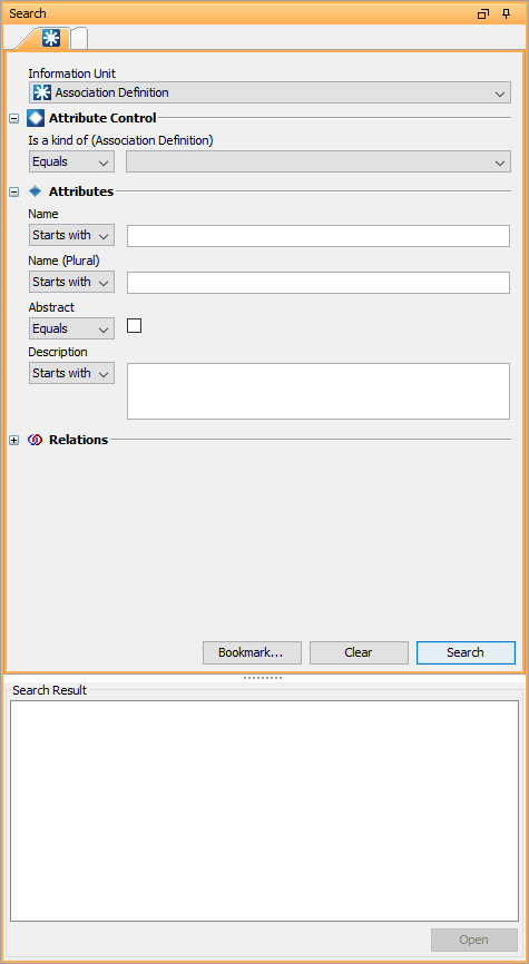
Search Panel
The application ![]() Search Panel is a tabbed panel where it is possible to have several searches open at the same time. The search panel is divided into two parts; the search query part and the search result part.
Search Panel is a tabbed panel where it is possible to have several searches open at the same time. The search panel is divided into two parts; the search query part and the search result part.
First, the information unit, in which the search should be executed, is chosen.
As the information unit is chosen search fields for Attribute Control, ![]() Attributes,
Attributes, ![]() Relations and
Relations and ![]() Attribute References (but not configurable attributes) are loaded.
Attribute References (but not configurable attributes) are loaded.
If the search unit is an individual unit like an ![]() Association (rather than a definition unit) a attribute control search field appears. The attribute control unit is a defining unit that controls the attributes (a definition or type). As a attribute control is chosen, attributes relevant to that unit are loaded. The panel only shows enabled attributes and references, and no attributes that lack a value set definition or a is a kind of altogether.
Association (rather than a definition unit) a attribute control search field appears. The attribute control unit is a defining unit that controls the attributes (a definition or type). As a attribute control is chosen, attributes relevant to that unit are loaded. The panel only shows enabled attributes and references, and no attributes that lack a value set definition or a is a kind of altogether.
Before each search field, a drop down list with appropriate search alternatives is shown. For a string (text) search for example, the list contains the following search qualifiers.
|
Qualifier |
Description |
|---|---|
| Starts with | Any text value that starts with the entered value |
| Contains | Any text value that contains the entered value |
| Equals | Any text value that is equal to the entered value |
| Like | Any text value that is equal to the entered value unless you use wildcards |
| Not equals | Any text value that is not equal to the entered value |
| Ends with | Any text value that ends with the entered value |
| Any value | Any text value which is not empty |
| No value | Any text value that is empty |
| Before | Any date value that is before the entered date
Only applicable for dates. |
| After | Any date value that is after the entered date
Only applicable for dates. |
| More than | Any numeric value that is more than the entered value
Only applicable for numeric values. |
| Less than | Any numeric value that is less than the entered value
Only applicable for numeric values. |
If the searched unit has a relation in both directions with other units, only one direction name occurs in the search panel, together with an arrow icon.
![]()
To search using the other direction, just click the arrow icon and the other direction name appears.
![]()
Wildcards and escape characters
The text-qualifiers Starts with, Ends with, Contains and Like all make use of wildcards, i.e. % for “any or no character” and for “any character”. The _Starts, Ends and Contains automatically adds these wildcards to the search criterion, e.g. if you enter ABC and use the qualifier Contains, the actual value used for searching is %ABC%. The qualifier Like does not add any wildcards automatically so if you don’t enter any of them into the search criterion it will have the same result as Equals. The table below shows some examples. The only available value is ABC. All queries are case insensitive.
| Starts with | B | |
| Starts with | A | |
| Contains | B | |
| Contains | D | |
| Ends with | C | |
| Ends with | B | |
| Like | B | |
| Like | B% | |
| Like | __C | |
| Like | _C | |
| Like | %A% |
If you for instance want to search for “all product codes that starts with A and then have a three random digit sequence, an underscore, and a three character sequence at the end, where the middle character should be F“. An example of such a code can be ABC123_EFG If you then use the qualifier Like and enter the following search criterion (a space has been added between every character for readability): A _ _ [ _ ] _ F . Please note that characters within [ and ] are escaped, i.e. the character (underscore) is treated as a wildcard unless you enclose ti within brackets. The same goes for %, i.e. if you want to search for the actual percentage character, you have to escape it, i.e. ABC% would return all values starting with ABC, whereas ABC[%] would return all values equal to ABC%.
Why use _Like_ instead of _Contains_?
The Contains-qualifier automatically adds the wildcard (%) at the start and end of the search criterion, e.g. A%C will become %A%C%. In this case the result can start or end with any or no character whilst if you would use the Like-qualifier the result had to have started with an A and ended with a C
With these search alternatives it is, apart from the ordinary search queries, possible to search for all units that do not have a attribute value, relation or attribute reference.
It is also possible to create sub queries. To search for all Generic Units where the name of the Generic Type contains “company”, for example, is done by choosing the drop down list alternative Search in the Generic Type list, typing “company” into the name field (with the Contains option for Name field) and pressing the button Search Query at the bottom of the new search window.
As the search query is complete and the search button pressed, the result of the query is shown in the search result part. The sort order is determined by a database setting and can not be configured in the application. By selecting one or more rows in the result and pressing the open button, the chosen units are opened in unit tabs. It is also possible to expand a unit directly in the list of results, without opening it in a unit tab. This works much like a simple navigator, simple because it can not be filtered.
Press the button Bookmark… to bookmark the search query for future reuse.
Press the button Clear to clear all search fields, except the information unit search alternative.
Search examples preparations
The example below requires you to have a simple structure where you can apply your search criteria. The examples only cover a small portion of the different combinations you can create, however, it is intended to be an introduction to what you can and can’t do. The data and structure below is very basic and is intended to be as simple as possible not to cloud the intent of the exercise.

Create the Generic Type A, which in turn classifies B, C and D. Create a Generic Unit for each type, i.e. A:1, B:1, C:1 and D:1.
Create an attribute with the type String for each type and name them Attribute A, B, C and D.
![]()
Attribute are inherited by the Classifies-relation so the type D should have four attributes as depicted in the navigator below.

For every Generic Unit you’ve created assign a value to each attribute, i.e. for the unit A:1 set the value A:A, for unit B:1 set the value B in the attributes Attribute A and Attribute B etc.

If you open the generic units in the Temporary Matrix the values should be distributed as depicted above.
Example 1 - Search by Attribute
The most basic and perhaps frequently used search criteria are to search on the information unit’s attributes. A (non-configurable) attribute is static and cannot be altered dynamically. In essence it is the same as a database column. The advantage is that the query is fairly simple and fast and is used to narrow down the result where you finally pick the desired entity to open for editing.In order to be able to search for anything at all you first have to decide what to search for. Select Generic Type under the Information Domain combobox.

When you have selected the information unit you want to look for the available attributes is added to the search panel as possible search criteria.

As you can see the attributes Name and Data Owner becomes available. If you perform the search without any criteria, all generic types will be present in the result. If you add a search criterion in the Name-field, e.g. A, the result will only contain generic types where the Name Starts with A.

Example 2 - Search by Configurable Attribute
In order to be able to use a configurable attribute as search criterion you have to select the type which defines it. Select Generic Unit as information unit and select the type A.

When you do so the attribute A becomes available in the search panel. If you select the type D, all of the attribute defined by D and its super classes, i.e. the types that classifies D becomes available. In this example Attribute A, B, C and D.

Similarly if you perform a search all generic units that are defined by the selected type, and its sub-classes, will appear in the result.

In this example all generic units in the result is of the type A, although their inheritance spans over several types, e.g. A to B to C and D.
If you add the search criterion _ (underscore) which means “any character” into the attribute D, only the generic unit that has the attribute and matches the criterion is included in the result, i.e. the generic unit D:1.

Change the values of the attribute B to B for all applicable units.

Select the type B and enter the search criterion B into the field for attribute B.

All generic units which is of the type B and matches the search criteria is present in the result, i.e. B:1, C:1 and D:1.
Example 3 - Search by Relation
Using relations as search criteria is very powerful although sometimes tricky to make viable combinations and to comprehend the result.In our simple structure we only have one relation to make use of and that is the Classifies / Is a kind of-relation. If you select the information unit Generic Type and navigate to the relation drop down box called Is a kind of. Select the type B and perform the search.

All generic types that is of the type B is present in the result, i.e. C and D.
Add a consist of-relation between the generic units B:1, C:1 and D:1 according to the image below.

Change the information unit to Generic Unit and navigate to the relation search criterion Is a part of.

If you perform the search the units that is a part of B:1 is included in the result. You can reverse the relation to search for units which consist of B:1, however, in our example there are no units that consist of B:1, so the result will be empty. If you select the unit D:1, the result will be C:1, i.e. C:1 consist of D:1.

Example 4 - Search by Qualifier
The drop down box available for each search criterion enables you to set the search qualifier. There are a set of options depending on the type of the attribute. For instance the qualifiers More than and Less than are only applicable for numeric values while Before and After only for dates. However, the qualifiers Any value and No value allows you to search for objects which lack a specific value and or relation. In the previous example, Search by Relation , you specified a unit that was contained in another one. If you change the search qualifier to Any value, you would get all units that are contained in another one.

Similarly you can set the qualifier to No value, i.e. the result will contain units that is not contained in another one.

This feature allows you to retrieve units where an attribute value or relation exists or not. This is very handy if you want to get groups of units which are missing a value or relation, or the opposite.
Example 5 - Search by Sub-query
In addition to selecting existing attributes, attributes and relations, you can use a sub-query for specific field. Select the information unit Generic Unit and select the Search… option in the Attribute Control field. You will be presented with a new search dialog where you can enter arbitrary search criteria, including other sub-queries.

This example is trivial, i.e. look for all generic types that starts with the letter A, however, all features are available in this search dialog as well. Please note that certain options are locked, i.e. when looking for attribute controls for a generic unit you can only look for generic types. Press the Search Query-button and you will be returned to the original search panel.

Important!
When you use a sub-query in the Attribute Control-field the inheritance is not included, i.e. if you would select the generic type A, instead of the sub-query, you would get the generic units A:1, B:1, C:1 and D:1. The inheritance feature is only applicable when you have one type, if you get many types, there is a possibility where you can have attribute controls which are not related to one another which makes it more or less impossible to create a meaningful query.
Bookmarks Panel

 Bookmarks are shortcuts to units and search queries.
To add a bookmark, press the bookmark button in the toolbar, right click any unit and choose Bookmark this or simply drag the unit from any navigator (search result or unit navigator) to the desired folder and row in the bookmark tree. To re-sequence a bookmark, just drag it to its right position in the tree.
To open a bookmark, just double click on it.
Renaming or deleting a shortcut does not affect the unit itself. The shortcut is renamed by clicking anywhere on it to select it and then either clicking on it again, this time on the text, or by pressing F2 on the keyboard, to set the text in edit mode. To save the new name, press enter. Leaving the edit mode by clicking somewhere else reverts the name. Removing the entire name from a shortcut gives the shortcut the unit name again.
It is also possible to bookmark a search. Define the search in the search tab and press the button Bookmark… Name the search and press the Ok-button and the search appear in the bookmarks tab with a search icon.
The unit tab

All units, persons for example, are shown in unit tabs in the main area of the window.
A unit tab consists of several sub tabs, for example General, Navigator, Connections, Graph and Change Log. Different types of units may have different sub tabs.
The bottom right part of the tab shows information about the kind of unit the instance is of, the context it is created in, the date and time when it was created, and if it is deleted, the date and time of deletion.
TIP!
You can easily move between tabs using the keyboard; use Alt-key + Right or Left arrow.
If the tab unit has been changed, but not saved, this is indicated by a asterisk (*) in the tab header ![]() . If such a tab is closed, the user is prompted to save or discard the changes before it is closed.
. If such a tab is closed, the user is prompted to save or discard the changes before it is closed.
Units may be opened simultaneously and grouped at the users will through the Tab menu. It is also possible to change the order of the unit tabs by dragging and dropping the tabs to the left or right of adjacent tabs.
General tab
The general tab consists of fields for the unit icon and attribute values.

Icon
If the unit does not have an icon of its own, it automatically inherits it from its unit (shown with a link). Press the link to open that unit. Inherited icons may not be deleted, only overridden. To override an icon, press the lookup button. This brings up an image load window.
Searching for the image in inorigo® Model Builder brings up the standard inorigo® search window. Searching the image on the computer brings up a standard Windows open dialog to enable upload of images to inorigo® Model Builder.
The image uploaded is stored in the Resource unit, where it may be administrated as any other unit.
Images are saved in three sizes; a full, a medium and a small size. The full size image is available by clicking on the image on the general tab. The medium size (with a maximum of 64 x 64 pixels) is used for display of image attribute values on the general tab. The small size (with a maximum of 16 x 16 pixels) is for showing icons on unit tab headers and in navigators.
Icon Inheritance
It is possible to specify icon heritage in a elaborate manner, and the rules are as follows.
- If no icon has been specified the default rule is to use the icon set for the class, i.e. the type, e.g. Generic Unit, Specific Unit, Association Definition etc. All units that are of that class will get that icon unless anything else has been specified.
- The next rule is to use the first icon that is found on an inorigo® entity that classifies this unit. For example if the Association Definition Project Portfolio is a kind of Portfolio and Other Unit, the algorithm will use the first icon that has been set on any of the Association Definitions that classifies Project Portfolio.
Modify the Portfolio unit to have a different icon. The icon for the Project Portfolio will now change.

Note!
The order of the is a kind of-relations are honored. Change the sequence of parent relations for the Association Definition Project Portfolio on the Connections-tab by selecting “Is a kind of” under Available connections, selecting the parent whose icon Project Portfolio should have, make sure it is on the top (using the arrow buttons) and save.

Use the icon which is set by the defining entity to be used by its instances, i.e. you specify on the definition what icon would be used by the instances. For example a Generic Type defines a Generic Unit (top down) and a Specific Unit instantiates a Generic Unit (bottom up).
Create an Association with the type My Project Portfolio as depicted below.

As you can see the newly created unit’s icon does not get the definition’s icon by default, you will have to specify it. Open the Project Portfolio object and go to the Connections-tab. Select Instances in the drop down Connection (under Applicable Properties) and specify the instances icon by pressing the lookup button. This way all instances of Project Portfolio will have the specified icon.

Change the icon into something meaningful as in image above.
The icon for the unit has now changed.

Important!
The rules for setting an icon (instantiate, classifies or implements) are inherited. For instance if you create a new generic unit which is a kind of Project Portfolio, all of the rules that have been setup for Project Portfolio‘s connections are inherited to the new sub-class.
3. If none of the above rules apply, the application will look for any implemented by-relations attached to the unit. If such a relation exists, it will check if the partner object has specified its implementers to use a particular icon, i.e. the same algorithm as for the classifies-relation. Create a new Vehicle Sedan and a new (unattached) Generic Unit Drivetrain.

Create an implemented by-relation between Drivetrain and Sedan and specify an icon for units that implement Drivetrain, e.g. ![]() .
.

If there are no rules set on the Car-object, the implemented by-relation will set the icon on the Sedan-unit.

The Drivetrain-icon is probably not the best illustration for a Sedan, so we decide to specify that all objects that are classified by Car should get the car-icon. Open the Connections-tab and select the connection Classifies and pick the appropriate icon.

The icon for the Sedan-unit will now change since the classifies-relation overrides the implements-relation.

Icon Inheritance Summary
The main purpose of the icon inheritance functionality is to be able to assign icons in a more flexible manner than before. You want to be able to assign icons to many instances based on rules rather than assigning an icon for every entity. The table below describes the rules for assigning an icon to an inorigo® unit.
| 0 | No icon rules have been specified. | The inorigo® entity uses its class’ icon, e.g. if the object is a Generic Unit the icon assigned to the class Generic Unit (CoConcept) will be used. |
| 1 | A unit classifies another one, e.g. A classifies B and B is a kind of A. | The entity B will inherit A‘s icon. |
| 2 | A unit implements another one, e.g. A is implemented by B. | The unit A will get the icon that has been specified for unit B‘s relation implemented by. |
| 3 | A unit instantiates another one, e.g. the Generic Unit A instantiates the Specific Unit A:1. | The instance A:1 will get the icon specified for the unit A‘s instance definition, i.e. the relation type where this unit is Attribute Control for its instances. For example a Generic Unit is an instance of Generic Type and Generic Unit instantiates Specific Unit, and so on. |
| 4 | A unit classifies another one and the unit’s classifies-relation specifies which icon to use. |
In a similar manner as specifying the instantiates-rule, you can set the icon to be used by units that is a kind of (classifies from the parent’s point of view) this unit. If an icon has been specified for the Classifies relation in Connection tab for a unit, this overides the relation Is a Kind of that the childs have to their Parent(s). In the tree-structure image below, let’s pretend it is a Classification structure. Object 3 has a Classifies icon in Connections tab while 1 and 2 has not. Object X will still get the icon from object 3. If the Classifies icon is removed from 3, object X will get its icon from (Is a Kind of) 1. Note! The instantiates and classifies-relation never coincide, i.e. a unit cannot instantiate and classify another unit with the same relation. |
| 5 | You explicitly set an icon on an inorigo® object. | If you explicitly set an icon on an inorigo® object, it will supersede all of the rules described above. |
As a consequence of the icon inheritance you are required to set the order of a unit’s parent relations, i.e. if a unit is a kind of A and B, you have to set which should be first. This is done in the Connections-tab of the unit in question.
When the algorithm for determining the icon checks for any classifies, instantiates or implements-relations it will use the first found, i.e. the type of the relation is used to determine precedence, not the order of the relation. If for instance unit B is a kind of A and C and A has set the classifies-relation to have a specific icon. B implements C, which has set a specific icon for units that implements C. In this scenario the icon set by A (classifies) will override the icon set by C (implements), regardless if B‘s is a kind of-relation sets unit C before A.

The search algorithm for looking up the nearest icon specification looks as follows, i.e. 1 has highest priority and falling and it is assumed that the left most unit (or relation) has the highest priority (lowest parent sequence).
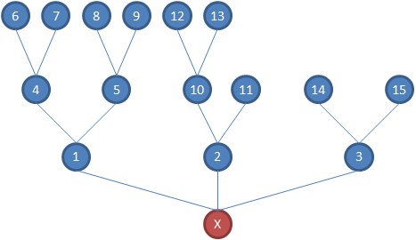
A unit’s heritage is displayed at the bottom of the edit-panel.

The icons displayed are defined as follows.
| 1 | The unit’s icon | |
| 2 | Icons for units that directly classifies this unit, i.e. units higher up in the classification hierarchy are excluded. | |
| 3 | Icons for the units that this unit implements. | |
| 4 | Icons for the units that defines this unit, i.e. units higher up in the classification or definition hierarchy are excluded. | |
| 5 | The icon for the class (or type). | . |

External Link
If an attribute has the type External Link, you are able to open the link by pressing CTRL while left clicking on the editable field. If the entered value is an absolute file path, starts with “C:” for instance, it will be converted into a valid URL, e.g. file:/C:/path/to/file. If the value cannot be validated it will be underlined and red, otherwise it will be in blue, e.g. http://www.ortelius.com.

The link also has a different appearance in the navigator and by right clicking on the node you will be presented with the option to follow the link in your default browser.

You are also able to open external links from inorigo® Application Builder, however, the context menu functionality recognizes if the selected value is a string and a valid URL; if that is the case the user is presented with the option to open the URL in the associated program.

Navigator tab
The navigator tab shows the unit and its attribute values ( ![]() ), attributes (
), attributes ( ![]() ), relations (
), relations ( ![]() ) and associations (
) and associations ( ![]() ) in a tree to enable navigation. Upward relations (
) in a tree to enable navigation. Upward relations ( ![]() ) and downward relations (
) and downward relations ( ![]() ) are shown with special relation icons.
) are shown with special relation icons.

The strength of the navigator is the ability to expand the tree nodes. Expanding a tree node expose the unit attributes and relations. They may in turn be expanded to give a complete picture of how the information model fit together.
The navigator tab also allows the user to create- and delete relations to other units, much as the connections tab does. Right click on a unit and a menu, the right click menu, will appear. The menu items displayed varies depending on user rights, context and if the unit is the top tree node (the tab unit) or if it is further down in the tree.

The first menu items consist of all the relations the user is allowed to create with the unit. The items are grouped according to the kind of units that the relation is created with. For most of the relations it is possible to connect the unit to either an existing- or a new unit. If a relation with an existing unit is chosen, a search window is opened. If a relation with a new unit is chosen, a “create new unit”-window is opened. When the Ok button is pressed, the new unit is both created and related to the tab unit. In order to change unit connections without saving them immediately, use the connections tab. Nothing is saved in that tab until the save button is explicitly pressed.
The next three items allow the user to open the unit in a tab, a dialog window or a Matrix.
The item Delete… deletes the selected unit(s).
If the unit right clicked is not the top tree node, but further down in the tree, the menu also contains the items Edit relation… and Disconnect…. Edit relation allows the user to for example change the sequence of the relation. Disconnecting a unit from the tab unit only removes the relation between the two; it does not delete the object itself.
The item Copy… copies the selected unit, while the option Copy id put a copy on the clipboard of the unique Global identifier in database.
The item Bookmark this adds a unit shortcut to the bookmarks tab.
The navigator has a filter at the bottom of the tab, sliding open when clicking on it. Clicking the filter headline again closes the filter.

The filter allows the user to choose what the navigation tree should and should not show. The top section of the filter shows filter options regardless of the information in the navigator tree. The bottom section on the other hand, shows information specific filter options. As the navigation tree is expanded and new units are revealed, their relations are added to the bottom section to allow the user to filter on specific relations.
Top section filter options are described in the table below.
| Show Bundles |
Initially checked to show relations of the same kind bundled together ( |
| Show Bundle Names | This option is only valid if Show Bundles is unchecked. Initially unchecked to hide unit relation names. Checked, all relations are prefixed with the relation name. |
| Show Upward Links | Initially checked to show all unit relations, both up and down. Unchecked, only downward links are shown. |
| Show Values |
Initially checked to show unit attribute values ( |
| Show Attributes |
Initially checked to show unit attributes ( |
| Show Bundle Size | This option is only valid if Show Bundles is checked. Initially checked to show the number of relations bundled. Unchecked, the numbers are hidden. |
| Simplify Names | This option is only valid if Show Bundles is checked. Initially unchecked to show, in parenthesis, the definition unit to which the relation points. Unchecked, the definition unit is hidden. |
| Show System Bundles | This option is only available if the system user role is Sysadmin. It shows technical information with no usefulness to regular users. |
It is possible to make global filter settings from the menu Options – Navigator.
Attributes tab
The attributes tab allows the user to define attributes.

To add, remove, edit or sequence attributes, use the buttons on the bottom of the attribute tab or right click on the appropriate item and select an action. If you double click on an attribute the edit dialog will appear.

Warning
Do not give (two or more) attributes the same name, since that will cause problems when for example referring to one of them from an expression.
Maneuvering in the attribute matrix is very similar to common spreadsheet applications, with the slight exception of the different functionality of the Home-button:
| Move around between cells | Keyboard keys Up / Down / Right / Left |
| Open attribute panel |
Keyboard Enter or Edit button ( |
| Move between fields in attribute panel | Keyboard Tab |
| Move to the topmost cell | PgUp |
| Move to the bottom cell | PgDn |
| Move to the cell to the right (unless you are in the rightmost cell) in attribute list | Keyboard Tab |
| Move to the last cell in the row | End |
| Select the whole row | Home or click in left margin |
| Move attribute |
Button up ( Alternatively use the keyboard keys to navigate to the attribute. Hold down Ctrl button and and use Up and Down keyboard keys to move the attribute. Release the Ctrl key when finished. |
| Edit | F2, double click or first character of value to input. Use Esc key on keyboard to exit Edit mode.
If the edited filed is a List of Values (LoV) field, select a value using arrow Up and Down keys and apply value by using Enter key. |
| Copy | Select cells + Ctrl + C |
| Cut | Select cells + Ctrl + X |
| Paste | Select all target cells or simply the initial cell + Ctrl + V |
| Fill down | Select source cells (topmost) and target cells (below) + Ctrl+ D |
| Fill down Series | Press Shift+Ctrl+D to create a series of values where each new row will be increased by one. Supported classes are:
|
| Delete values | Select target cells + Delete |
| Delete rows |
Select target row(s) + Delete or press the delete-button ( |
| Add new rows |
To add one new row: Press the add button ( |
| Reload |
Ctrl + R or press the reload button ( |
| Save |
Ctrl + S or press the save button ( |
| Export to Excel |
Ctrl + E or press the “Export to Excel button ( |
Attribute properties

The attribute properties window consists of the following fields.
| Class | The type of value the attribute holds. It is either a primitive (listed below) or it points at a unit in which case that unit is chosen in the drop down list. Primitives:
|
|
Instance of Only applicable to Association Definitions and where the attribute class is an inorigo® instance, see Association Attribute Properties |
The selection contains all instances of a particular type. Replaces the Valueset-functionality for inorigo® entities. In order to be able to find out what entity can be part of an association, it is required that the selection of possible values is structured. The valueset can be based on one or several queries and randomly selected objects. |
|
Is a kind of Only applicable to Association Definitions and where the attribute class is an inorigo® type, see Association Attribute Properties |
The selection contains all sub-classes of a particular type, including all levels in the hierarchy. Replaces the Valueset-functionality for inorigo® entities. In order to be able to find out what entity can be part of an association, it is required that the selection of possible values is structured. The valueset can be based on one or several queries and randomly selected objects. |
| Name/Alias | The name of the attribute. If the attribute is inherited through a classification structure, it is possible to give it an alias (see picture below). |
| Remark | An attribute remark. |
| Sequence | The sequence of the attribute in relation to other attributes. |
| Disabled | Disabling the attribute makes it disappear from the general- and navigator tabs of the unit that has inherited the attribute. |
| Unit of Measure | The unit of measure in which values should be entered. |
| Multiplicity | Multiplicity allows for a complex setting of number of values. The multiplicity field could for example show: “1, 4..6, 10..12, 50” which means that one, four, five, six, ten, eleven, twelve and fifty occurrences of the attribute value are allowed. Specify ranges with .. between the minimum and maximum value and separate many values or ranges with a comma. 1.. means that there must be at least one occurrence and that maximum is unlimited. |
| Read Only | True if the attribute value may only be read, not altered. Complement a read only value with a fixed value (see below). |
| Valueset | If the user should be limited to certain values, these values may be defined in a valueset. See below this table for instructions on how to create, change and delete a valueset. |
| Default Value | If specified, the chosen value will appear in the drop down list per default. The user is allowed to change it though. |
| Fixed Value | If specified, the chosen value will appear in the drop down list, but may NOT be changed by the user. |
|
Method It is not recommended to use this property, since it is not possible to pass parameters to the method when inovked. Use an Expression to call the method instead! |
This property enables an attribute value to be calculated, or otherwise processed. It is only visible if the user has rights to define methods (the change flow setting in the user preferences). |
| Expression |
Use an Expression to calculate or otherwise process attribute values. Important! When calling a method from an Expression, make sure to send all method inputs as parameters, for example: “$CALL(“[Method]/[methodName]”, @Attribute1, @Attribute2)“. If the call is invoked from a browser (when for example adding a new unit in an Application on the web) the method execution environment has no other information than the one sent via parameters. For the same reason, it is not possible to Set an attribute value in a method when invoked from a browser, it is only possible to return the value to the attribute (so it appears as value on the attribute that invoked the method). |
|
Singular Name Only applicable to |
Used when denoting an association from this attribute’s perspective (point of view), e.g. used in the context menu when to create a new association. |
|
Plural Name Only applicable to |
Used when denoting a bundle (collection) of associations from this attribute’s perspective (point of view), e.g. used in the search panel for attribute references. |
|
Instance Presentation Only applicable to |
How to present the association from this attribute’s perspective (point of view). |
If the attribute is inherited through a classification structure, the properties window shows the attribute properties throughout the heritage.

In order to override inherited values, check the checkbox in front of the field. The field then becomes active. If an inherited value should be deleted, the checkbox must be unchecked. Just removing the text in the remark field for example, keeps the heritage, but sets it to blank.
The only property not possible to override is the Unit property.
Valueset
A valueset limits the possible values to choose from as the attribute is presented on the general tab. Press the valueset definition button ( ![]() ) to open the valueset window.
) to open the valueset window.
How the valueset is created depends on what kind of value the attribute holds/points at. If the attribute holds a simple value, a primitive, (such as a string or an integer) it is possible to enter in simple strings or integer values.

Simply type the value in the text box to the right and press the << button. Sequence or delete the added values by using the buttons underneath the valueset list to the left. To use an existing valueset, press the open button in the top left corner.
If the attribute points at another unit, a person for example, the right hand side of the window changes into a search panel.

It is possible to create a valueset that is either dynamic, through one or many search queries, or static, with given units.
A dynamic valueset is dynamic in the sense that a valueset query is executed at the time the user accesses a General tab where the attribute is shown. Thus, the result may vary from one occasion to another, without having changed the valueset itself, only the data the valueset reads. Build a dynamic valueset by defining a search query and pressing the add search button ( ![]() ). Name the query and press Ok. It is recommended to test the query first though by pressing the Search button and verifying the result.
). Name the query and press Ok. It is recommended to test the query first though by pressing the Search button and verifying the result.
Instance of / Is a Kind of
If a Valueset is specified together with Instance of/Is a kind of, a Valueset is always considered before Instance of/Is a kind of (CPFPDT-2247).
A static valueset on the other hand, is a valueset with preselected units. Only the units explicitly chosen in this window appear as possible values in the General Tab. Find the units in the search panel to the right, select them in the search result and press the add unit button ( ![]() ) to add them to the valueset. The icon on the add unit button reflects the unit the attribute points at.
) to add them to the valueset. The icon on the add unit button reflects the unit the attribute points at.
It is possible to add both search queries and single units. The first column in the valueset list to the left shows the value type.
Connections tab
The connections tab allows the user to get an overview of the possible relations the unit may have with other units. This is shown in the tree to the left.

Select a relation in the tree and all the units that this unit has that relation to appears in the list to the right.
To create a new relation, select the kind of relation in the tree and press the plus button at the bottom of the tab. Pressing the plus button brings out a sub menu with the alternatives Create new… and Add existing…

Use the new alternative if the relation should be made to a unit that is not yet created and the existing alternative if the relation should be made to an existing unit. To sequence the relation, select it and press the Up- or Down button. To disconnect a relation, select it and press the minus button.
Note!
This does not delete the unit itself, only removes the relation between the units.
To be able to create a relation between two units, the application must be set up to allow that kind of relation between those kinds of units. This is done in the Relation Specifier, found in the application menu tab – Basic Data – Relation Specifier.

Choose the unit to create the relation from in the drop down list “From” and to in the drop down list “To”. Add and remove a relation by selecting it and pressing any of the move buttons in the middle ( ![]()
![]()
![]()
![]() ). Sequence added relations with any of the sequence buttons (
). Sequence added relations with any of the sequence buttons ( ![]()
![]()
![]()
![]() ).
).
Methods tab

Method can be used for a variety of purposes, integration; import or export, calculation, validation, messaging etc. The method tab is only visible for the Process Unit Definition entity, i.e. a method is always associated with a process. Generally you identify a method by the name of the process unit definition and the method, e.g. My Process Unit Definition / My Method. Unless you specify a method name, the method engine will assume that there is a method called main. If no such method exists, an exception is thrown stating that the method is missing.
The methods tab contains several components and this is a short description of their purpose.
- Primitives
- This panel contains all primitives that can be executed within a method. A primitive performs a (relatively) simple and well-defined task. The functionality ranges from adding two integers to creating Excel- and XML-documents to performing complex queries to the inorigo® database.
- Methods
- The panel contains a list of all methods associated with this Process Unit Definition. You create and delete a method by clicking on the plus or minus-button at the bottom of the panel. The filter box at the top allows you to filter the list of methods.
- Method panel
- The method panel is where you “drag and drop” your primitives and in- and output links to define your method. You specify in- and output parameters to the method by holding the CTRL-key down and left-click on the left hand side of the panel. In the picture below there is a single input visualized as an empty white circle. The procedure is the same when you want to add parameters to a primitive statement inside the panel; hold down the CTRL-key and left click. When you want to submit a value from one statement to another, select the in- our out-parameter, press the SHIFT-key and left click on the next parameter. IF you want to create a syncronization line, hold down the CTRL-key instead of the SHIFT-key.
The Back and Forward button at the top left of the panel allows you to navigate through the history of selected methods. The Name text field allows you to change the name of a method. - Right click on the panel and you will get the available primitives as a popup-menu along with the possibility to Copy the selected primitives or entire method, and Paste it into another method or instance of Inorigo® Model Builder.
Please note that the input and output does not automatically follow the method, need to be added manually. - If you drag and drop another method onto the panel a CALL-primitive is created with the proper name. If you press CTRL at the same time a FOR_EACH-primitive is created. Pressing CTRL+ALT while dragging the method will create a SUBROUTINE-statement with the correct method name. If you drag and drop a bookmark (query) onto the methods panel, two primitives are created, OBJECT and SEARCH. This behavior saves you the effort to add the objects separately since you always want to associate the two primitives with each other.
- To add in- and output parameters to a statement you should position the mouse cursor directly to the left (input) or right (output) of a statement until the cursor changes to a +. Hold down CTRL and left-click with the mouse and a new parameter should be added. You can also select a statement and press CTRL+I to add input and CTRL+SHIFT+I to remove resp. CTRL+O and CTRL+SHIFT+O for output-parameters.
- The method panel is where you “drag and drop” your primitives and in- and output links to define your method. You specify in- and output parameters to the method by holding the CTRL-key down and left-click on the left hand side of the panel. In the picture below there is a single input visualized as an empty white circle. The procedure is the same when you want to add parameters to a primitive statement inside the panel; hold down the CTRL-key and left click. When you want to submit a value from one statement to another, select the in- our out-parameter, press the SHIFT-key and left click on the next parameter. IF you want to create a syncronization line, hold down the CTRL-key instead of the SHIFT-key.
- Execution
- The execution panel allows you to execute the currently selected method. The Execute method executes the method on the client, while the Execute process on server submits the task to be performed by inorigo® Engine. Executed on the server, the application waits for the method to complete in the background, allowing the user to continue working with other parts of the application. The user is also granted an option to abort the execution.
- #* Background processes should be performed by the inorigo® Engine while other tasks can be performed on the client. Please remember that if you have references to external resources such as files or URLs, they are probably not the same from the inorgio® Engine’s perspective as from your client machine.
- If you check the Debug only one primitive statement will be executed and then you have the possibility to Step to the next one or Abort. This is intended for debugging purposes.
- The Log check box is a way to reduce the amount of log-information that is shown in the log text area. In some cases the sheer number of method and primitive invocations may cloud the overall picture of the execution. It is recommended to uncheck the box if you expect the method to be a long running execution; the output may consume all memory thus making the invocation impossible. Please note that if the method is executed by the inorigo® Engine, this has no effect.
- The Commit-flag instructs the method runner to perform a commit or not. In many cases you are only interested in retrieving data, not updating it, then the commit-flag should be set to false. You can consider it to be a “read only”-flag, i.e. no updates will remain.
- The Breakpoints-table contains breakpoints set on different primitives. Select a primitive statement and press CTRL+B and the breakpoint will appear in the list. Press CTRL+B again to remove it. You have the possibility to activate / deactivate them and if you double click on the breakpoint the denoted primitive will be selected and the method will appear in the method panel. If you have an active breakpoint the method will execute until it encounters the breakpoint and then it will stop. Breakpoints only have effect when running the method on the client.
- Statement properties
- The properties panel allows you to specify input to the different primitive statements.

Real Process Unit Occasions
Running a method now only creates a Real Process Unit Occasion if the method is run on the server and the commit-flag is true (real occasions are not created for sub rutines).
If a method fails, the Real Process Unit Occasion get a failed message in the remark field.
Consult inorigo® Primitives, inorigo® Integration Setup and inorigo® Methods for more in-depth information about how to construct methods.
Change log tab

The level of change log details is set in the Server tab of the System Settings available from the Options menu.
To undo a transaction the log level must be set to 2 or higher. Only transactions that consist of delete- and/or disconnect actions may be undone. Clarification: if the transaction contains an insert-, update- or connect action in addition to the delete- and/or disconnect actions, the transaction may not be undone. Other than that, if any of the objects involved in the transaction are updated after the transaction was executed, the transaction may not be undone.
If log level is set to 1, the right click menu may show undo, but cannot undo any actions, since there are none logged.
The upper part of the tab holds the fundamental data. It consists of the following fields:
| ID | The global database ID of the unit. |
| Class | The kind of unit. |
| Context | The context the unit resides in. |
| Valid from | The date and time the unit is created. |
| Valid to | The date and time the unit is deleted. |
| Rights | The rights set on the object. If no rights are set, all rights are set to true (i.e. all users have all rights). |
The lower part shows the actual change occasions (transactions). Expand the transactions to see them in as much detail as the server settings has allowed it to be logged.
To Undo a transaction, right click the transaction and choose Undo transaction.
![]()
The only changes possible to undo are those involving the deletion or disconnection of a unit from another unit. In addition to that, to undo a change, none of the units involved may have been changed.
Log options
There are three kinds of logs; Application log, Integration log and Server log.
Application Log
Application log level can be set in System Settings / Server / Log Level. This is the log that is displayed in the Change log.
- 0 – No logging
- 1 – Log that a transaction took place
- 2 – Logging which type of action on an object that took place (Create, Read, Update, Delete Execute).
- 3 – Level 2 + Full trace on attribute values before and after change. Recommended and default setting.
All logging actions on an object can be accessed by opening the object and displaying the Change log tab.
Most delete actions perform soft deletes i.e. when an object is deleted a Valid to-date is created, which means the object remains in the database, but it does not appear in any query results invoked from inorigo® Model Builder, since the Valid To-date is used as a search criterion. Hence there is no set time limit for storing objects which can be fully accessed from inorigo® Model Builder even after a soft delete.
Integration Log
When performing imports and exports it is possible to create log events for these kinds of transactions. The log events are accessible from inorigo® Model Builder.
Server Log
A log file is created in the installed server subfolder “los”. When the logfile has reached 1 MB a new logfile is created and the previous file is renamed. There is a maximum of 10 files, i.e. when the 11th is created the last one is removed. You can change these settings in the windows service wrapper files, e.g. wrapper.cof and the properties wrapper.logfile.maxsize and wrapper.logfile.maxfiles. If the server runs as expected there is little maintenance regarding logs. However, if you need to increase the log level for troubleshooting purposes you can do so by adding the application argument DEBUG=true. You can alter (or add) the application argument wrapper.app.parameter.nn=DEBUG=true where nn is a sequence number, in the wrapper*.conf-files used for initializing the application(s). The parameter is valid in all wrapper configuration files; Server, Engine and Web Services. You have to restart the application in order for the changes to have effect. It is not recommended to have DEBUG set to true unless you are troubleshooting the application since you will be unable to investigate events happening before the log files are overwritten.
Status bar
At the bottom of the application window there is a status bar.
![]()
It shows (from left to right):
| The logged on user | |
| Current Context | |
| Current application language with the locale within parenthesis | |
| Name of the application server: port number | |
| Client version and build number (a number derived from the versioning of the development environment) | |
| Memory available/Memory currently reserved for inorigo®/Maximum amount of memory that can be reserved. | |
| Today’s date and current time. |
As the client is waiting for a reply from the server, a blue square is displayed around the server symbol ![]() .
.
Temporary matrix
The temporary matrix is a tool to provide a quick and easy way to handle large bits of information in no time. The look and feel is similar to common spreadsheet-applications with which it also shares much of its controls for operations like copy, fill-down, cut, paste and delete data in multiple cells in one go. It also supports copy and paste data to and from spreadsheets. But beware – this is not a spreadsheet application. The content of the cells are richer, i.e. they may contain one or several inorigo® entities which may in turn control the behavior of other objects displayed in the matrix. So – there is a lot more under the surface than in an ordinary spreadsheet application.
The matrix is about offering the ability to handle units of information of different kinds, from numbers, text and images to geopolitical units or user defined objects with complex relationships to the world around them. Besides supporting rapid editing of large quantities of data, the matrix also gives the user the option of sorting the data and hiding or rearranging columns to increase overview.
Matrix overview

Each object opened in the matrix gets columns holding information on the icon of their type (in the first column), definitions ( ![]() ) when applicable, inherent attributes (
) when applicable, inherent attributes ( ![]() ), defined attributes (
), defined attributes ( ![]() ) and relations (
) and relations ( ![]() and / or
and / or ![]() ). By default the columns containing relations gets hidden, as they sometimes take up a lot of room and is not as often edited in the matrix; but these can easily be displayed.
). By default the columns containing relations gets hidden, as they sometimes take up a lot of room and is not as often edited in the matrix; but these can easily be displayed.
One exception exist though; the “Is a kind of” relation is displayed when applicable in the Generic Domain since it is commonly used (Generic Types, Generic Units and Association Definitions).
Following the icon and name in each column header is the information on the multiplicity of the data. For all units of information where the multiplicity has not been set in any way this will read as “[0..]”. Multiple objects in the same cell are separated by semicolon (;).
If any special ordering is set for any column its multiplicity information will be followed by an icon signifying ascending ( ![]() ) or descending (
) or descending ( ![]() ). The number 1 signifies that this sorting is the primary out of many possible.
). The number 1 signifies that this sorting is the primary out of many possible.
On top of the data grid is a search field for filtering. ![]()
Below the grid you find a delete button ( ![]() ) and an add button (
) and an add button ( ![]() ).
).
Editing data
Maneuvering in the matrix is very similar to common spreadsheet applications, with the slight exception of the different functionality of the Home-button:
|
Action |
Description |
|---|---|
| Move around between cells | Up / Down / Right / Left |
| Move to the cell below | Enter |
| Move to the cell to the right (unless you are in the rightmost cell) | Tab |
| Move to the topmost cell | PgUp |
| Move to the bottom cell | PgDn |
| Move to the last cell in the row | End |
| Select the whole row | Home or click in left margin |
| Edit | F2, double click or first character of value to input |
| Copy | Select cells / rows + Ctrl + C |
| Cut | Select cells / rows + Ctrl + X |
| Paste | Select all target cells or simply the initial cell + Ctrl + V |
| Fill down | Select source cells (topmost) and target cells (below) + Ctrl+ D |
| Fill down Series | Press Shift+Ctrl+D to create a series of values where each new row will be increased by one. Supported classes are:
|
| Delete values | Select target cells or rows + Delete |
| Delete rows | Select target row(s) + Delete or press the delete-button ( |
| Add new rows | To add one new row: Press the add button ( To add several new rows: Press the downward arrow on the add button and choose 5, 10 or enter a custom amount of new rows.  |
| Reload | Ctrl + R or press the reload button ( |
| Save | Ctrl + S or press the save button ( |
| Export to Excel | Ctrl + E or press the “Export to Excel button ( |
Beware that no changes, including deletion, will be committed until you have saved. If you regret the changes you have done since your last save you can undo them by reloading the data. Also note that you have to leave a cell after you have edited it for the system to beware of the change and to able to save that change. It is not possible to save only some changes while not saving others. This applies even if you have applied a filter or have hidden columns.
Notes on copying and pasting information from outside sources
Copying certain data from spreadsheets may require a little bit more effort due to its special formatting. In that case this formatting has to be reset:
- Select the data you want to copy from your spreadsheet application.
- Reset the formatting can be done through either of two ways:
- If you can find an Autoformat-option in your application (often accessible through the pull down menu: Format Autoformat): Select its none or no formatting-option and press OK. Check that your data is still selected.
- The alternative approach: Copy the data. Either do a Paste Special to a new spreadsheet or a normal paste to any simple (that does not support formatting) text editor. Now select again what you just pasted.
- Copy selected data
- Select the target columns/rows in the temporary matrix in inorigo® Model Builder.
- Paste
Although this procedure does the trick in most cases, situations exist where a more manual approach is necessary. One such is when you need data from cells containing line breaks in certain spreadsheet applications. To properly get the data from these cells you have to enter each cell, select and copy its content, enter (not merely select) the target cell in the temporary matrix and then paste.
To paste a value from an outside source to a cell that allows multiple values is no different than pasting data to any other cell. To paste multiple values from an outside source to a single cell in the matrix is also very simple. First check that the column (the attribute) of the target cell supports the amount of values you want to paste. Then, before you paste, just make sure that all values are delimited by a semicolon, much like multiple respondents in an email.
Copy/Paste of nameless units
The temporary matrix also supports pasting units that doesn’t have a name. A nameless unit is for example an Association Instance or a Specific Unit without a name.
The copied values must either correspond with the association presentation names (as plain text) or, also valid for Specific Units, their Global IDs.
Examples: The Employment Association instance, e.g. “Jens is employed at ACME.inc”, may now be pasted either as a plain text or with its Global ID (e.g. “74E520EA-F152-430A-B59C-AD6F4A8205F4”) found on the Change Log tab. The unnamed Specific Unit “#3FBBA67D-1775-1700-8C3F-A322009A4D26 (Chair)” may be pasted with its presentation name (“#3FBBA67D-1775-1700-8C3F-A322009A4D26 (Chair)”) or just its Global ID (“3FBBA67D-1775-1700-8C3F-A322009A4D26”).
Selection and row deletion
Row Selection

As the user selects entire rows by clicking (and dragging) in the row header part of the Matrix component, the row header will render as a blue pressed button. The data area will render a selection border around the outer perimeter of the selected cells.
Cell Selection

As the user selects individual cells by clicking (and dragging) in the data area part of the Matrix component, the row header will render as a gray pressed button. The data area will render a selection border around the outer perimeter of the selected cells. Also there will be a bold border around the last cell selected, this indicates the focused cell (which is not applicable during row selection).
The rendering of row header color is dependent on component focus, so while other windows or Applications are in focus rather than the Matrix component, the Matrix might render gray row headers even if rows were selected. They will become blue again as soon as focus is switched back to the Matrix component.
Row Deletion
To delete an entire row, the row must be selected (it is not enough to select all cells in the row). If the row is selected, deletion of it is enabled both via the delete button on the keyboard and the delete button underneath the matrix ( ![]() ). If the row unit may not be deleted (due to links to other units) the delete button underneath the matrix is disabled and pressing the keyboard delete button has no effect.
). If the row unit may not be deleted (due to links to other units) the delete button underneath the matrix is disabled and pressing the keyboard delete button has no effect.
Deleted rows are not immediately deleted, but only marked for deletion until the matrix is saved (see the image below). The exception to this is if a row is added, but not yet saved, and then deleted. In that case the row will be immediately removed.

To undo (not yet saved) deleted rows, select the rows marked for deletion and press the delete button again. This will remove the row deletion marks. It is also possible to reload the entire matrix ( ![]() ), but then all changes are lost.
), but then all changes are lost.
Cell Content Deletion
When cells are selected (as opposed to rows) the delete button underneath the matrix is disabled and the delete key on the keyboard can be used to clear cell content.
Note that any change in the matrix will mark the Temporary matrix* with an asterix.
Adjusting the view of the data
There are three different ways to set how and what data is shown in the matrix: filters, column-setup and sorting.
Applying a filter
Applying a filter to the data in the matrix is an easy way to find and view only the rows matching a certain text typed criteria. This can be done straight away by typing in the filter box.
For more advanced filtering, press the magnifier icon to reach filter settings. The first section of these settings set which columns the filter applies to. The second section sets whether the filter should differentiate between upper- or lowercase letters. The third concerns whether filter should permit the use of joker characters (like % and *) and the forth is how the filter will match your filter string: from the start, exact match or everywhere match.
Adjusting columns setup
To rearrange the order of a column just hover the mouse pointer above its header, hold the left mouse button down and move the column to wherever you like.
To set the width of a column just let the mouse pointer hover a bit to the right or left of the border connecting two columns. The pointer will change into a double-sided arrow and you are ready to adjust the width. To auto resize any or all columns, hover above its header and right click to get a menu with these options present.
In this right click-menu you also find options of hiding current column, showing/hiding all columns and all relation columns. At the top is the option More… which brings up a dialog box containing the column names and checkboxes, making it easier to set the visibility status for many columns at the same time.
Add calculated column…
The option “Add calculated column…” available from the context menu, allows you to insert a new column right on the spot where command was issued (context menu). The expression field make use of the input object (@Y_Object) and can invoke any epxression function available in inorigo®. The example below shows where you have an object which has the attributes Amount and Tax and I’m interested in showing the tax percentage, i.e. 100 * (Tax / Amount).

The option “Remove this column” available from the context menu in Edit mode, allows you to delete a calculated column right on the spot where command was issued (context menu).
It is not possible to remove any non-calculated column, i.e. columns with data from definitions ( ![]() ) when applicable, inherent attributes (
) when applicable, inherent attributes ( ![]() ), defined attributes (
), defined attributes ( ![]() ) and relations (
) and relations ( ![]() and / or
and / or ![]() ).
).
Web rendering enables other interpretation than default; Link and Html.
| Link | Render column cells as a link to web page. In the Application, the content of the cell will be a clickable link, i.e. the text string “http://www.ortelius.com” will be converted into http://www.ortelius.com |
| Html |
Render column cells as html. In the Application, the contents of the cell will be interpreted as html, i.e. text string “My favorite color is |
The example matrix below shows how you can add dynamically calculated cell values to the matrix.

Sorting the data
To sort the data, click the column heading you want to order by. The first click will set up a sort of ascending type. A second click on the same header will change the sort to descending and a third ends the sort on that column.
To sort rows based on many columns at the same time, hold down CTRL and click as described above. There is no limit to how many additional sorts you can apply.
Note that the sorting you set up wont effect coming changes to cells and rows. The way to reenact the sorting is simply to redo the clicking of column headers you want to order by.
Notes on concurrency
In inorigo® Model Builder it is possible for multiple users to be logged in and work simultaneously with the same or connected sets of data. This becomes even more important when it comes to working with data through the matrix. Whenever any changes has been made from outside to the data you are currently working with, the matrix will automatically update the concerned cells and rows. The only exception to this is if a user is currently in edit mode in a cell with data that is updated from somewhere else. In this case the matrix will report unsaved changes to the cell, even if the user hasn’t made any changes, because the value in the cell differs from the saved value. If the user saves his value will be saved, if the user reloads the value in his cell will be as consistent as the rest of the cells with the current “real” data.
Limitations
There are a couple of known limitations of the matrix:
- It is not possible to view/edit objects from different information domains within the same matrix. This is a consciously set limitation and exist for a couple of reasons. First off this paves the way for a use of the matrix which encourages a cleaner look and overview of the information being worked with in the matrix. With just a couple of objects from different information domains the matrix would be quite stretched horizontally and the user would need to, either do a lot of scrolling, or showing/hiding of attributes (or relations) as they moved down and up their rows of different data. Another reason is that a limitation like this makes the matrix more maintainable behind the scenes and thus easier to improve both in the areas of functionality and performance.
- For this version of the matrix the handling of complex attributes is no longer supported. Legacy still support the existing complex attributes to avoid inorigo® upgrade issues. It should be considered to remove complex attributes at customer sites.
- Beware when deleting many units at the same time. Since the matrix performs a single delete for every unit, the operation may be time-consuming, i.e. although the application seems to hang, the operation continues in the background. Currently there is no “bulk”-delete, if this functionality is deemed to be important it may also be implemented in future version of inorigo®.
Resources
The Resource unit (previously “Image”) is used for storing images and any other type of documents. A pre-requisite is that the resource type exists in inorigo® since it is used to determine the usage of the resource, i.e. if the resource is an image, it will be used to represent the object, otherwise the resource type’s image will be used by default. The “Resource type” unit can be accessed in the “Basic Data”-menu and the following are available in the base installation.
|
|
avi | video/msvideo |
|
|
doc | application/msword |
|
|
docx | application/vnd.openxmlformats-officedocument.wordprocessingml.document |
|
|
gif | image/gif |
|
|
jpeg | image/jpeg |
|
|
jpg | image/jpeg |
|
|
mid | application/x-midi |
|
|
mov | video/quicktime |
|
|
mp3 | audio/x-mpeg |
|
|
mpg | video/mpeg |
|
|
application/pdf | |
|
|
png | image/png |
|
|
ppt | application/vnd.ms-powerpoint |
|
|
pptx | application/vnd.openxmlformats-officedocument.presentationml.presentation |
|
|
rtf | application/rtf |
|
|
txt | text/plain |
|
|
xls | application/vnd.ms-excel |
|
|
xlsx | application/vnd.openxmlformats-officedocument.spreadsheetml.sheet |
|
|
zip | application/zip |
You can add any number of resource types; however, there are some special rules associated with some of them.
- MIME-types starting with “image/” are considered to be an image and thus used to render icons and images in inorigo®.
- The resource types for text (txt) and Excel (xls) can be used for input data to Application Builder.
To add a new resource type, choose New -> Basic Data -> Resource type. Specify the File extension (for example the image file extension tiff) and find the Content type for tiff on for example Wikipedia. Give the resource type an appropriate icon (if the resource type is an image, use the mime_img_64 resource). Once saved, it is possible to upload resources of that type.

It is not recommended to remove any of the pre-defined resource types from inorigo® sine it may limit or damage existing functionality.
Resources general tab
The General tab of a Resource unit looks slightly different from other General tabs, in that it has an image representation of the selected resource.

If an image is selected you have the opportunity to have three different sizes, any other resource type only have the “full” size. The search button will open a file-dialog where you can select the desired file with the limitation that the resource type already exists, i.e. a file type which has an unknown file-extension may not be selected. The image below displays the general tab when an image has been selected.

Note
To optimize application handling of images, only save the image once (in the appropriate size), and leave the two other image-size-boxes empty (the system will handle a downsize automatically). If the medium- and/or small sized images should be different from the full size (in other aspects than mere size), upload them separately by clicking the lookup buttons in each box. The Full Size should always be populated.
The Full Size should ALWAYS be populated.
The other two are intended for icons, to be used ONLY when you require a special representation for your image in smaller contexts. It might be that your original image is huge and causes lots of overhead when it is to be used as an icon, or the original image does not scale very well and therefor you need a custom icon version of the image.
Other than that, it is advised to leave the small versions empty, they will only cause redundant overhead and occupy space in the database and on the server.
The medium size field allows for a 64 x 64 pixels large image for representation of the full size image on the General tab. Double click on the representation image on the General Tab to open the full size image.
![]()
The small size field allows for a 16 x 16 pixel image for representation of the full size image in the navigation tree.
![]()
Image types supported are GIF, JPEG and PNG. Any other file type will cause an error message.
If you double click on any of the resource representations in the image areas the file will be saved in the system temp directory, e.g. “c:users{user}AppDataLocalTemp” as read only, and is opened in the associated program (if any). Optionally, click on and drag the image to any location.
Selecting a Resource
When you are selecting a resource you will get the option to either select a file or an existing resource, see image below.

If you select a file which has the same name you will be prompted to either update the existing resource or to create a new one. This feature prevents the risk of having duplicate resources in inorigo®.

Another way of adding a new Resource is to drag the source file into the Full Size area in Model Builder. The Resource Type will be detected automatically and a Name suggestion will also be provided as illustrated below:

The dragging of Resources is bi-directional, which means it is possible to drag the Resource back to any client computer.
Resource attribute
If you have a Resource attribute defined it will be depicted on the General tab as shown below.

If you choose to select an existing or create a new resource you can do so by clicking the find-button.
Resource Update
An update of a resource will immediately refresh the display of the resource throughout the application. There is one exception though; static icons & images in user interface elements (such as buttons, menus and toolbars) are NOT guaranteed to be refreshed directly as a resource is updated. If the icon is located within a document tab or an Application a mere reopen of the tab or Application will show the new icon. In other cases it may even require a restart of the entire application in order to refresh certain elements.
Expression Editor
Specifies the expression to use to fetch content data.
Expression Editor
The Expression Editor will simplify the readability of expressions as it checks for inconsistencies and helps you with some guidance and basic validations to create the expression.
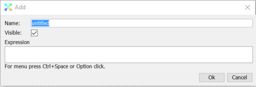
Note, the Visible option is not always available, it depends on the context expression is used, e.g. it is useful when writing expressions for map Info panel.
The Functions context menu options will show all the available Expression Functions
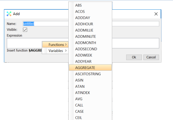
and they are inserted in Expression field as they are selected.
There are a few shortcuts to some of the most common operations/variables/functions used;
| Ctrl-G | $GET |
| Ctrl-I | @item (the Source object in map configuration) |
| Ctrl-N | “name” |
| Ctrl-R | @record |
Variables – Verso View will give the list of available default variables, user defined variables and dataset(s) as input to new Expression Variables in view;
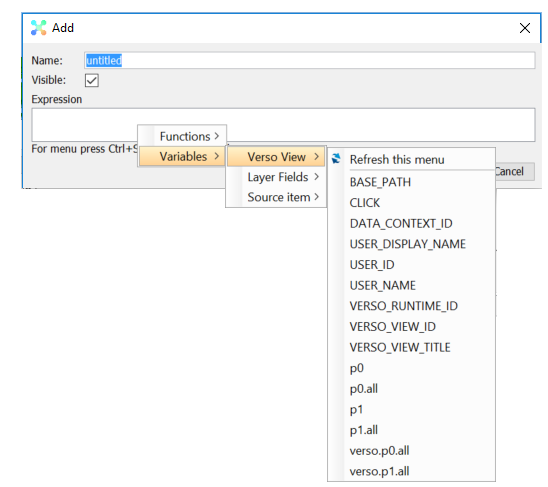
Example that shows the available items defined in view
Refresh this menu
Sometimes the contents of the context menu are not updated, especially for some Variables and Datasets that require calculations to be updated, hence the Refresh option to update the list.
While configuring the World Map, additional options are available – the fields that was fetched from the Layer URL;
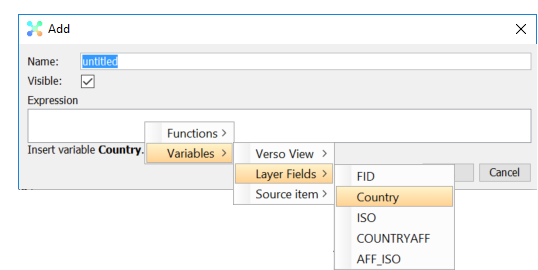
Example showing the available fields from Layer to be used in an expression
and also the items that are referenced by the Source setting for World Map;
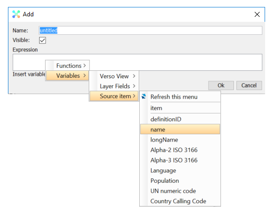
Example that shows the available items to be used in an expression, in this case a filter box that list Countries from the Geographical Area domain.
The status bar at the bottom of Expression Editor will provide a possible cause of error in expression. The expression will also be marked with red color as seen in the examples below;

Example 1, missing parenthesis
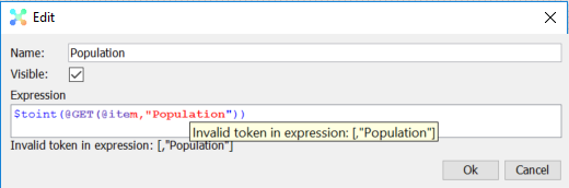
Example 2, wrong symbol in front of expression function
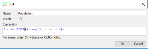
Example 3, no error, and as one can see the parenthesis is being paired for better readability